Circuit diagram example
4.4 TIA Portal configuration
Safety engineering with AS‑Interface in the SIMATIC ET 200SP, including typical circuit diagram
Function Manual, 08/2020, A5E44991382002A/RS-AB/002
33
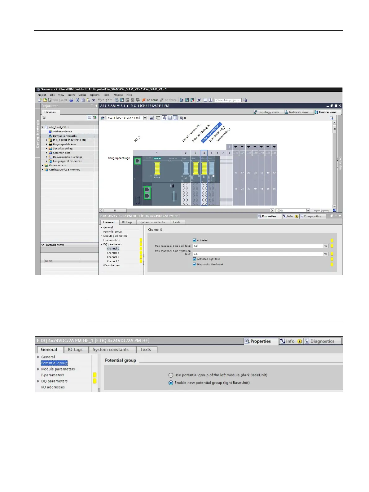
9. Insert the F-DQ 4x24VDC/2A PM HF module on the right of the F-CM module, and activate
its 1st channel in its "DQ parameters".
10. Insert the DI 8x24VDC HF module and a server module on the right of the F-DQ module.
Figure 4-6 Complete configuration of the ET 200SP station
Note
The setting of the correct base units (light or dark) must be observed for all four modules.
Figure 4-7 Selecting the correct base unit

 Loading...


