Specifications
6.7 Connection examples for Enable switch and STOP button
Mobile Panel 177 (WinCC flexible)
Operating Instructions (Compact), Edition 07/2005
6-19
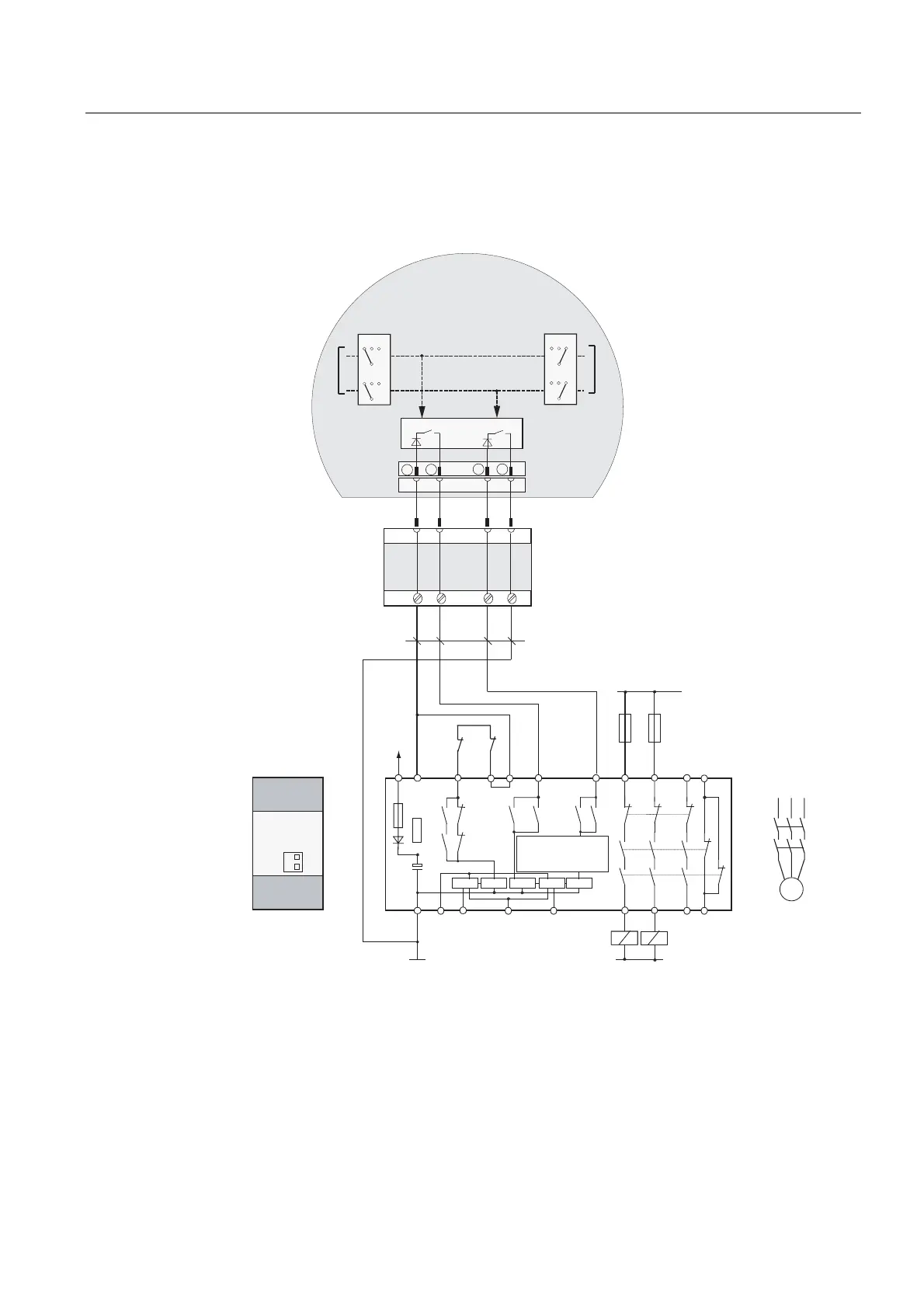
Connection example 1: Enabling switch with monitoring device ELAN SRB-NA-R-C.27/S1
The following figure shows the connection of a monitoring device ELAN SRB-NA-R-C.27/S1
to the enabling switch of the Mobile Panel.
)
6
.
.
.
. .
.
6
.
.
.
.
.
.
.
& & 6 6 6 6 6
/'/
/'
)
$W $W
6
6
/ / /
.$
.%
0
;
ದ
ದ
'&
9
.$
.%
/
*1'
.$
1
*1'
.$ .%
0RELOH3DQHO
(63
(60
(63
(60
(/$1
65%1$5&6
&RQQHFWLQJFDEOHV
PLQPP
&X
7ZRHQDEOLQJVZLWFKHV
VWDJHDQGFLUFXLWHDFK
(6OHIW (6ULJKW
&LUFXLW
&LUFXLW
(6&LUFXLW (6&LUFXLW
(YDOXDWLRQ
HOHFWURQLFV
7HUPLQDO%R[%DVLF
RU
7HUPLQDO%R[3OXV
&URVVRYHUFLUFXLW
UHFRJQLWLRQ
0RGXOHUHDU
Figure 6-18 Wiring diagram: Enabling switch with monitoring device ELAN SRB-NA-R-C.27/S1
S1 and S4 switches on the rear of the module must be at Position 0.
 Loading...