Specifications
6.7 Connection examples for Enable switch and STOP button
Mobile Panel 177 (WinCC flexible)
6-20 Operating Instructions (Compact), Edition 07/2005
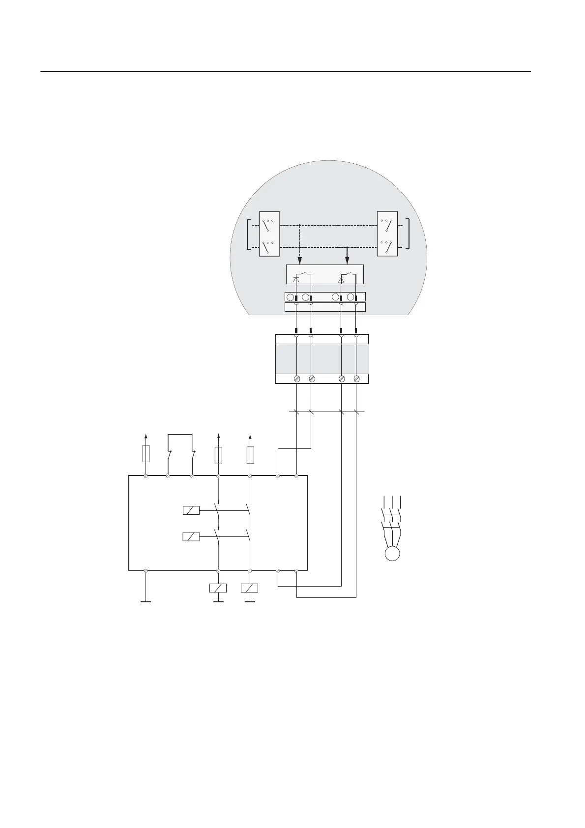
Connection example 2: Enabling switch on monitoring device PILZ PST1
The following figure shows the connection of a monitoring device PILZ PST1 to the enabling
switch of the Mobile Panel.
.
.
3,/=
367
$
;
ದ
ದ
$ ; ; 6
$
6 6
6
.$ .%
$W
$I
$W
$I
*1'
.$ .%
*1' *1'
9'& 9'& 9'&
0RELOH3DQHO
/ / /
.$
.%
0
(63
(60
(63
(60
&RQQHFWLQJFDEOHV
PLQPP
&X
7ZRHQDEOLQJVZLWFKHV
VWDJHDQGFLUFXLWHDFK
(6OHIW (6ULJKW
&LUFXLW
&LUFXLW
(6&LUFXLW (6&LUFXLW
(YDOXDWLRQ
HOHFWURQLFV
7HUPLQDO%R[%DVLF
RU
7HUPLQDO%R[3OXV
,QSXWFLUFXLW
,QSXWFLUFXLW
)HHGEDFNORRS
RU RU
Figure 6-19 Wiring diagram: Enabling switch on monitoring device PILZ PST1
 Loading...