Overview
1.2 Design of the device
SIMATIC IPC427E
14 Operating Instructions, 09/2017, A5E37454814-AB
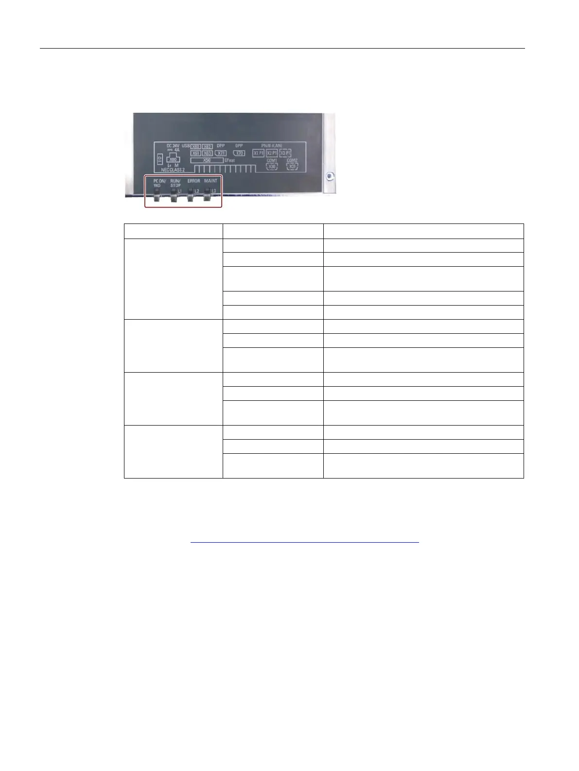
PC ON/WD Off -
BIOS ready to boot; PC running
Flashing green/yellow
BIOS in POST, power switch on
Watchdog status display: active
RUN/STOP / L1
Can be controlled by user program
Yellow Can be controlled by controller program (e.g.
ERROR / L2
Flashing red Can be controlled by user program or controller
MAINT / L3
Red Can be controlled by controller program (e.g.
For additional information on controlling the LEDs or the NVRAM with a Windows operating
system, please refer to Output register user LED L1/L2/L3 (read/write, address 404Eh)
(Page 122). Example programs for controlling the LEDs on Windows operating systems are
available on the Customer Support page of Siemens Industry Automation and Drive
Technologies. (http://www.siemens.com/automation/service&support)