Installation, connecting up, sources of problems
4.2 Connecting up
SCALANCE X-100
Operating Instructions, 04, A2B00060666D
47
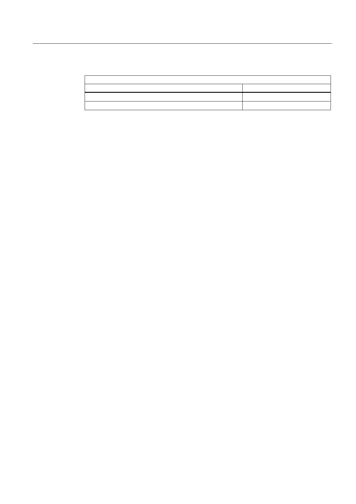
Table 4- 2 Pin assignment of the signaling contact
SCALANCE X-100
Pin number Assignment
Pin 1 F1
Pin 2 F2
The following errors/faults can be signaled by the signaling contact:
● The failure of a link at a monitored port.
● The failure of one of the two monitored power supplies.
The connection or disconnection of a communication node on an unmonitored port does not
lead to an error message.
The signaling contact remains activated until the error/fault is eliminated or until the current
status is applied as the new desired status using the button.
When the device is turned off, the signaling contact is always activated (open).
4.2.3 Grounding
Installation on a DIN rail
The device is grounded over the DIN rail.
S7 standard rail
The device is grounded over its rear panel and the neck of the screw.
Wall mounting
The device is grounded by the securing screw in the unpainted hole.
Please note that the SCALANCE X-100 must be grounded over one securing screw with
minimum resistance.
If a device of the SCALANCE X100 product line is mounted on a non-conducting base, a
grounding cable must be installed. The grounding cable is not supplied with the device.
Connect the paint-free surface of the device to the nearest grounding point using the
grounding cable.

 Loading...


