S5-115F Manual Addressing
The module is then addressed as follows:
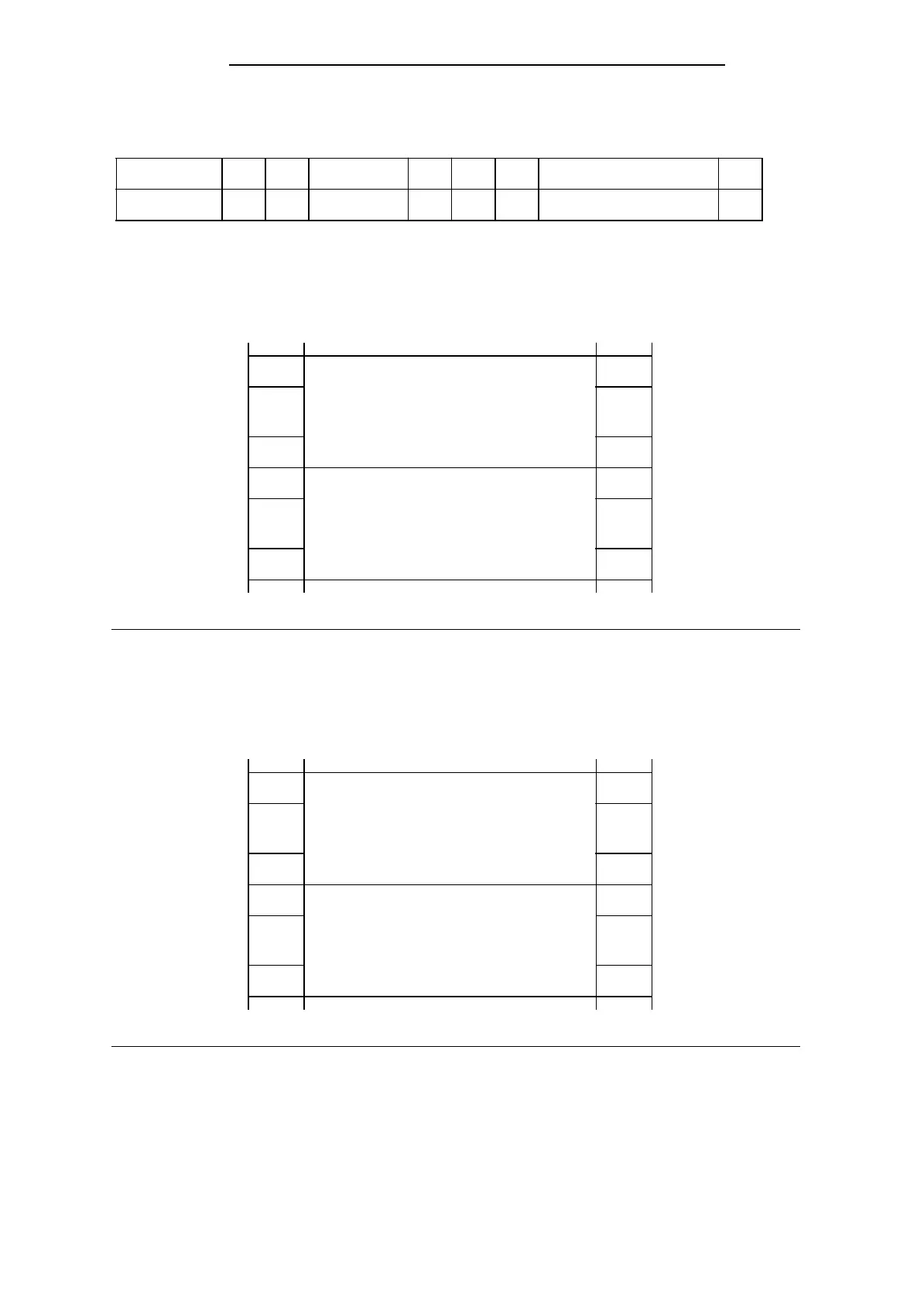
Bit No.
Address
0
46.0
1
46.1
2 . . . 7 8 9
46.7 47.0 47.1
10 . . . 15
47.7
5.3 Handling Process Signals
Input/output module signal states can be read from, or written to, the addresses shown in
Figure 5-4.
Analog modules
Digital modules
F000
H
F07F
H
F080
H
F0FF
H
0
127
128
255
Absolute addresses Relative byte addresses
Figure 5-4. Addressing Input and Output Modules
Digital module signal states are also stored in a special memory area called the process image. The
process image has two sections, namely the process image of the inputs (PII) and the process image
of the outputs (PIQ). Figure 5-5 shows where the process images are in the program memory:
EF00
H
EF7F
H
EF80
H
EFFF
H
PII
0
127
0
127
PIQ
Absolute addresses Relative byte addresses
Figure 5-5. Location of the Process Images
Process signals can be read or output either via the process image or directly.
EWA 4NEB 811 6148-02
5-5