S5-115F Manual Installation Guidelines
3.2.4 Interconnecting the Two Subunits
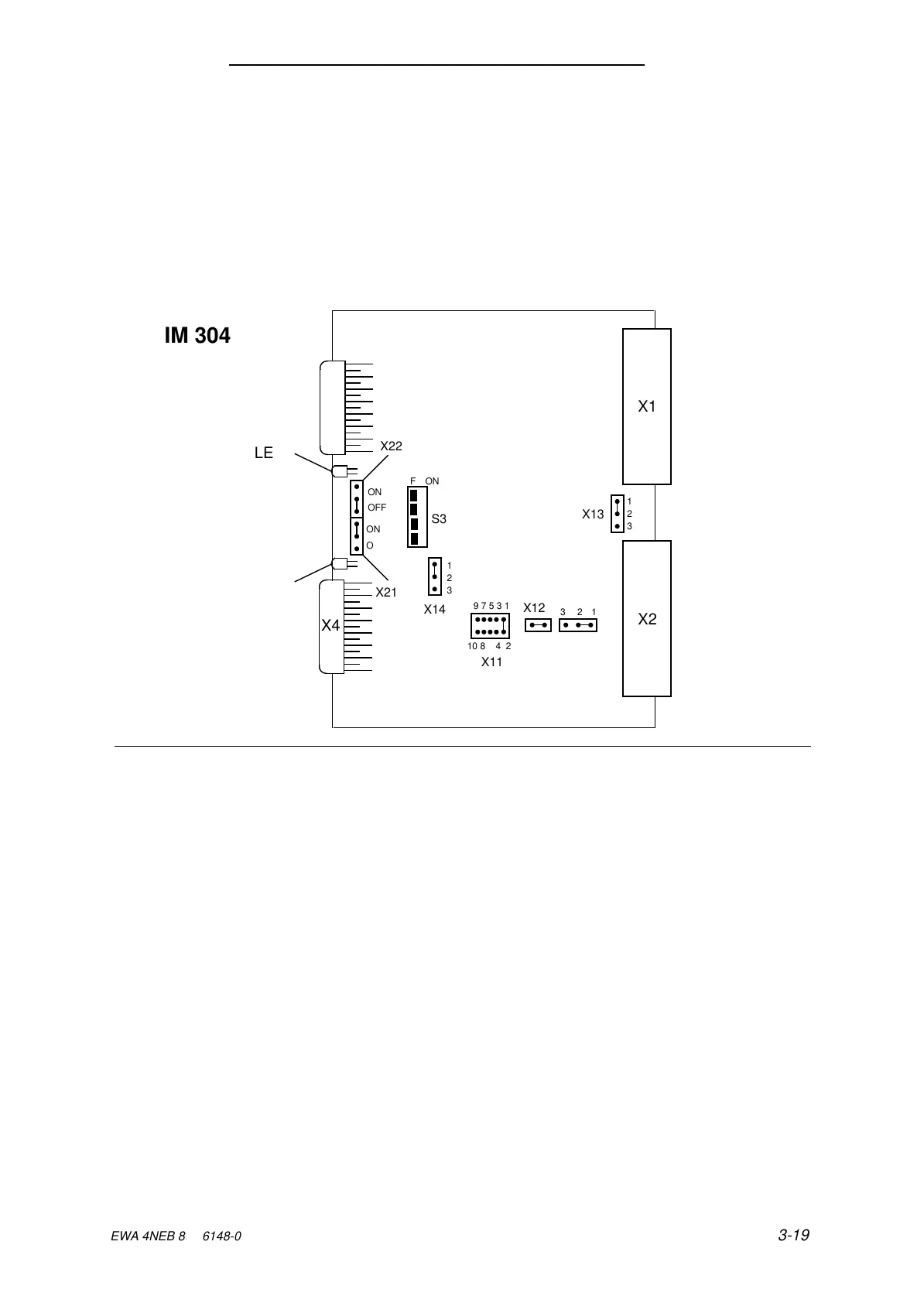
The two subunits are interconnected via an IM 304 / IM 324 parallel link. The IM 304 interface
module can be plugged into either subunit A or subunit B.
The IM 304 and IM 324 modules are connected to each other with the 721 connecting cable over a
maximum distance of 10 m (33 ft.). The cable is connected to the lower of the two interface ports.
Please use the switch and jumper settings shown in Figures 3-19 and 3-20 for establishing the
parallel link between the two subunits.
Figure 3-19. Switch and Jumper Settings on the IM 304-3UB11 for the Parallel Link
X15
X3
a
a
a
a
a
a
a
a
X2
12
a
a
a
a
a
a
a
a
X1
1
2
3
X13
a
a
a
a
X12
3
a
a
a
a
a
a
a
a
a
a
ON
OFF
a
a
a
a
a
a
a
a
a
a
a
a
a
a
a
ON
OFF
a
a
a
a
a
a
a
a
a
a
a
a
a
a
OFF ON
a
a
a
a
S3
1
2
3
a
a
a
a
a
a
a
a
a
a
a
a
a
a
a
9 7 5 3 1
X11
a
a
a
a
a
a
a
a
a
a
a
a
a
a
a
a
a
a
10 8 6 4 2
X21
X22
a
a
a
a
a
a
X14
LED2
LED1
X4
IM 304
EWA 4NEB 811 6148-02
3-19