S5-115F Manual Installation Guidelines
3 Installation Guidelines
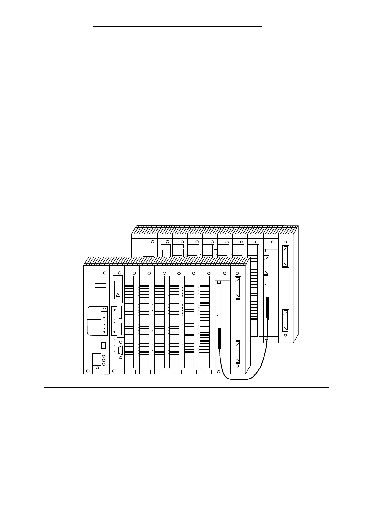
Programmable controllers of the S5-115F system consist of two central controllers to which one or
more expansion units can be connected if necessary. The modules that make up the S5-115F are
mounted on racks which are located in cabinets to reduce the effects of interference.
3.1 Mounting Rack
Various mounting racks are available to suit the performance or the degree of expansion the
control system is to have.
Each mounting rack consists of an aluminum mounting rail for fastening all modules mechanically
and one or two backplanes for connecting the modules to each other electrically. The module
locations (slots) are numbered in ascending order from left to right.
3.1.1 Central Controller (CC)
A central controller has a power supply module (PS), a central processing unit (CPU), and various
input/output modules (I/Os). Depending on requirements, digital or analog modules can be used.
Interface modules (IMs) are required when expansion units are used.
Figure 3-1. Programmable Controller without Expansion Units
A CR 700-2F or a CR 700-0 mounting rack is required for installing a central controller.
EWA 4NEB 811 6148-02
3-1