S5-115F Manual Rules Governing the Use of the S5-115F
10.9.5 Type 3 Digital Input Modules
Type 3 DIs have the following characteristics:
• Safety-related
• The input signal can be intermittent or non-intermittent
• They are operated in both subunits A and B (in two-channel configuration) and must have the
same module address in both subunits.
• The operating system checks the DI inputs once per test cycle to see if the DI modules can read
in a ”0” signal. To make the test, the sensor supply to deactivatable sensors is switched off and
non-deactivatable sensors are switched back on. Additional check digital output modules
(CH DQs) are required for this.
• Read loops with L PY and L PW are illegal in OB 2 and OB 13.
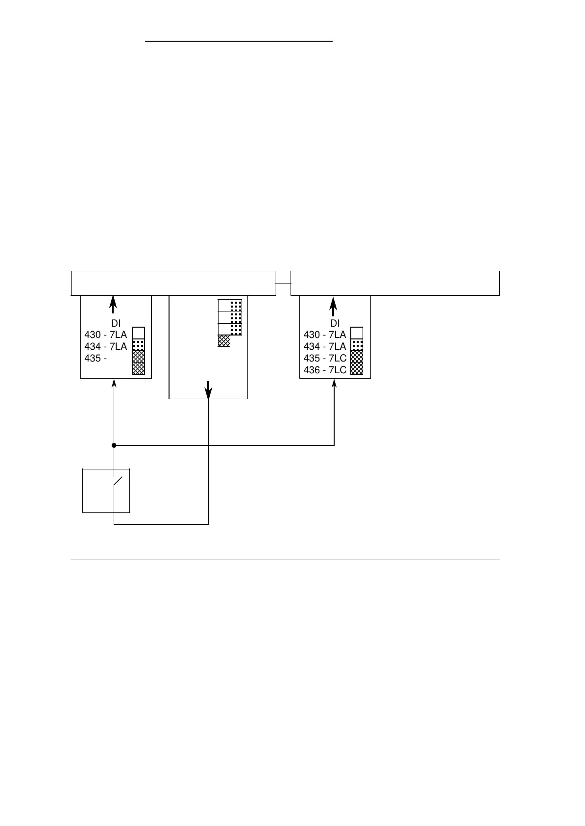
Connecting deactivatable sensors
Figure 10-9. Type 3 DI, Safety-Related, Non-Intermittent: Single-Channel,
Deactivatable Sensors
. . .
. . .
Subunit A Subunit B
Sensor
451 - 7LA
458 - 7LA
458 - 7LB
456 - 7LB
CH DQ
a
a
a
a
a
a
a
a
a
a
a
a
a
a
a
a
DI
430 - 7LA
434 - 7LA
435 - 7LC
436 - 7LC
a
a
a
a
a
a
a
a
a
a
a
a
DI
430 - 7LA
434 - 7LA
435 - 7LC
436 - 7LC
a
a
a
a
a
a
a
a
a
a
a
a
a
a
a
a
a
a
EWA 4NEB 811 6148-02
10-21