S5-115F Manual Analog Value Processing
6.6.2 Analog Output Modules
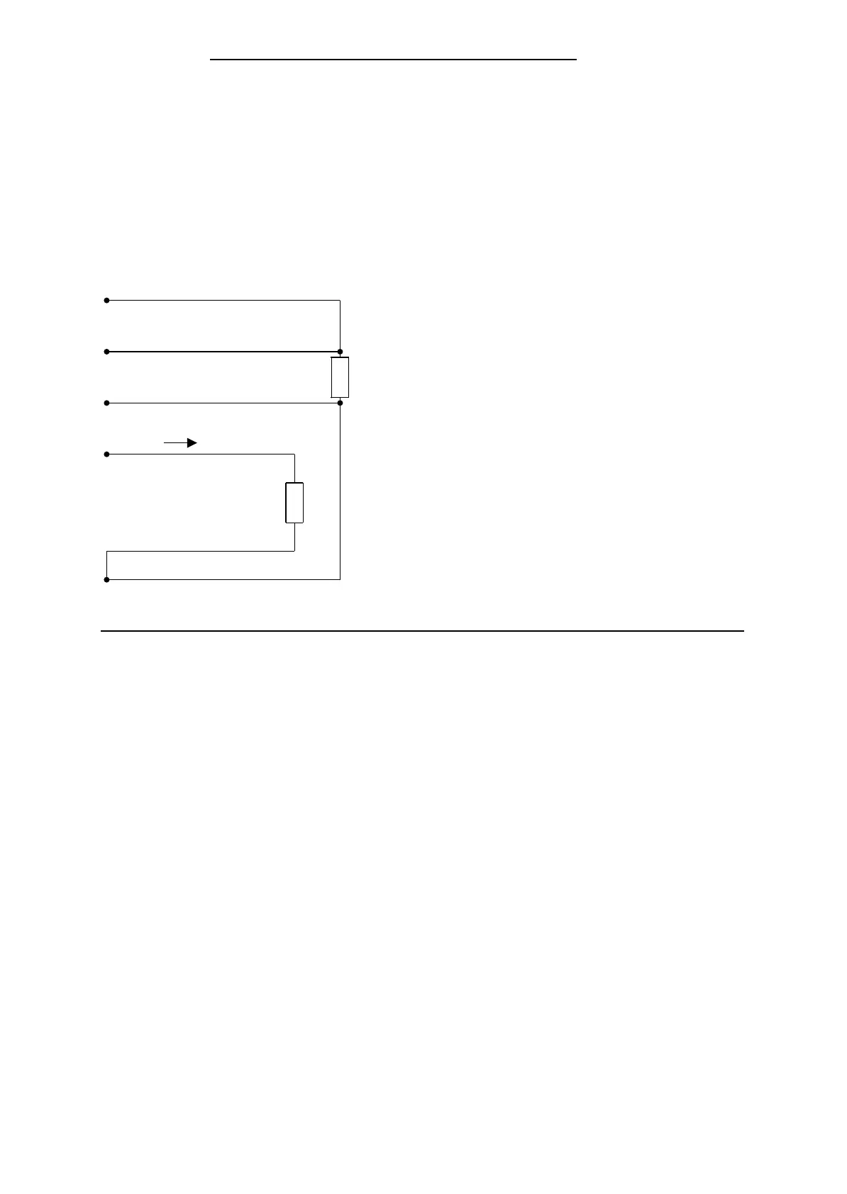
When loads are connected, high-resistance sense lines (S+/S-) measure the voltage direct at the
load. Then the output voltage is adjusted such that voltage drops on the lines do not invalidate
the load voltage.
In this way, voltage drops of up to 3 V per line can be compensated.
Figure 6-14 shows such a circuit.
Figure 6-14. Connecting Loads to Analog Output Modules
-
+
Load
voltage
QI (x)
M
ANA
QV (x)
S+ (x)
S - (x)
I
+
-
Load
current
QV (x) = Analog output voltage
QI (x) = Analog output current
S+ (x) = Sense line+
S - (x) = Sense line -
M
ANA
= Ground connection of the
analog section
x = Channel No. (0 to 7)
Equipotential bonding during test switching with the 470 analog output module
If you are using the 470 analog output module as a test analog output module, make the
following connection:
The L-terminal (pin 21) of the 463 analog input module to
the L-terminal (pin 47) of the 470 analog output module.
This creates a common reference potential.
EWA 4NEB 811 6148-02
6-29
 Loading...


