S5-115F Manual System Startup
Central Processing Unit
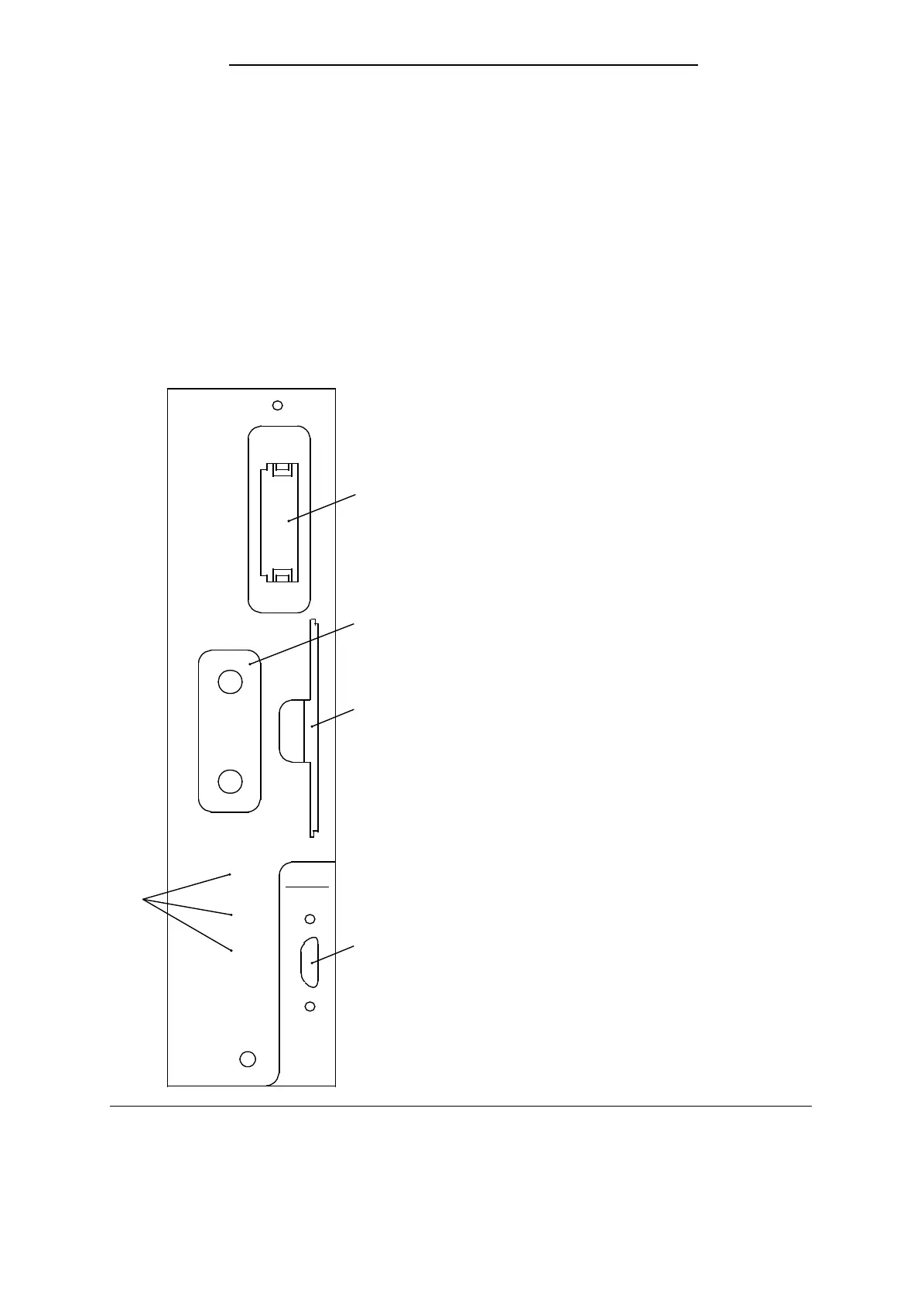
The following operator functions are possible on the front panel of the CPU:
• Plug in a memory submodule
• Connect a programmer (PG)
• Connect SINEC L1
• Select the operating mode
• Perform an Overall Reset
LEDs indicate the current CPU operating mode. A slot in the CPU front panel contains a plastic card
with the most important operating instructions for the PS and CPU. Figure 4-2 shows the front of
the CPU.
Receptacle for memory submodule
Control panel
Instruction card
Connectors for PG or SINEC L1 LAN
Fault LEDs
QVZ: Time-out
ZYK: Scan time exceeded
BASP: Command output disable
RN
ST
RN
ST
OR
QVZ
ZYK
BASP
115F
CPU
942
Figure 4-2. Front View of the CPU
EWA 4NEB 811 6148-02
4-3