Technical specifications
A.3 Digital I/O modules
Easy Book
Manual, 03/2014, A5E02486774-AF
293
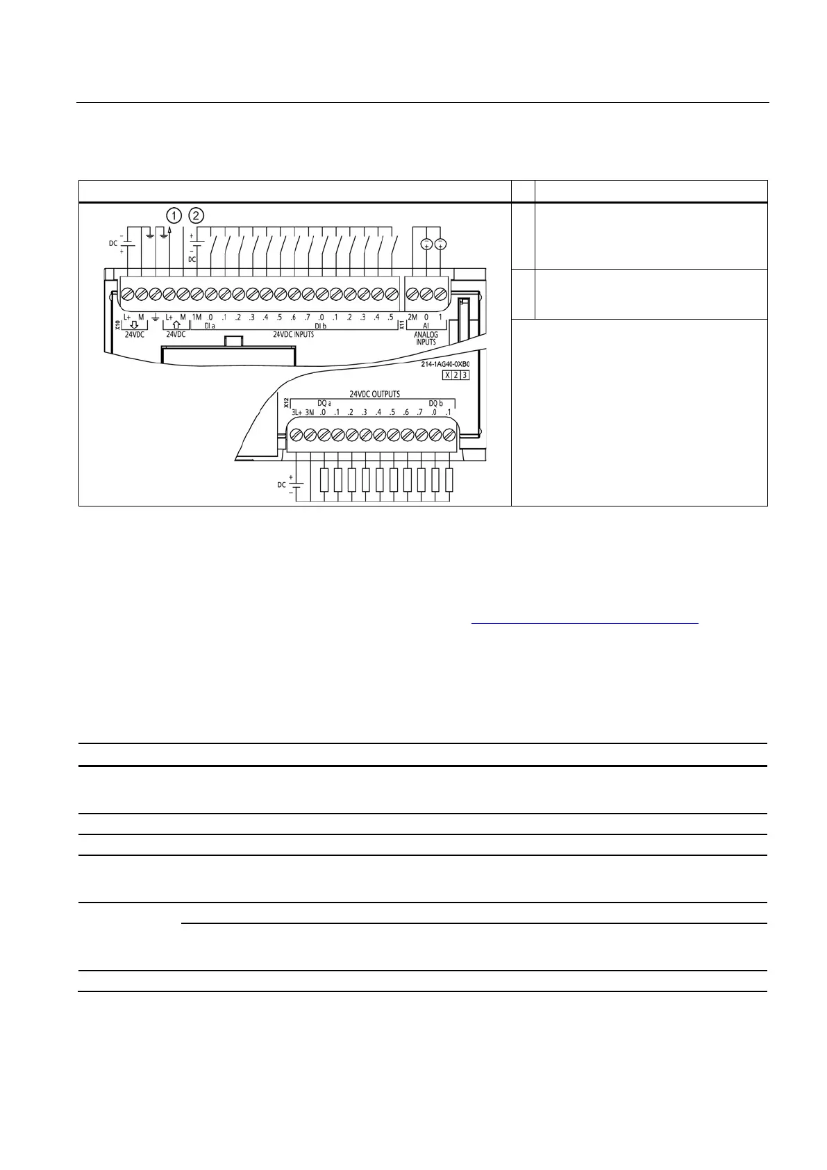
Table A- 13 Wiring diagram for CPU 1214C DC/DC/DC
①
24 VDC Sensor Power Out. For
additional noise immunity, connect "M"
to chassis ground even if not using
②
For sinking inputs, connect "-" to "M"
(shown). For sourcing inputs, connect
Note 1: X11 connectors must be gold. See
the S7-1200 System Manual, Appendix C,
Spare Parts for order number.
For a more complete list of modules available for S7-1200, refer to the S7-1200 System
Manual or to the customer support web site (http://www.siemens.com/automation/).
SB 1221, SB 1222, and SB 1223 digital input/output (DI, DQ, and DI/DQ)
Table A- 14 SB 1221 digital input (DI) and SB 1222 digital output (DQ) modules
Order number
• 24 VDC: 6ES7 221-3BD30-0XB0
• 5 VDC: 6ES7 221-3AD30-0XB0
• 24 VDC: 6ES7 222-1BD30-0XB0
• 5 VDC: 6ES7 222-1AD30-0XB0
Dimensions W x H x D (mm)
Power dissipation
• 24 VDC: 1.5 W
• 5 VDC: 1.0 W
0.5 W
Current
consumption
24 VDC
• 24 VDC: 7 mA / input + 20 mA
• 5 VDC: 15 mA / input + 15 mA
15 mA
4 outputs (solid state - MOSFET)

 Loading...


