3-16
S7-200 Programmable Controller, CPU 210
C79000-G7076-C235-01
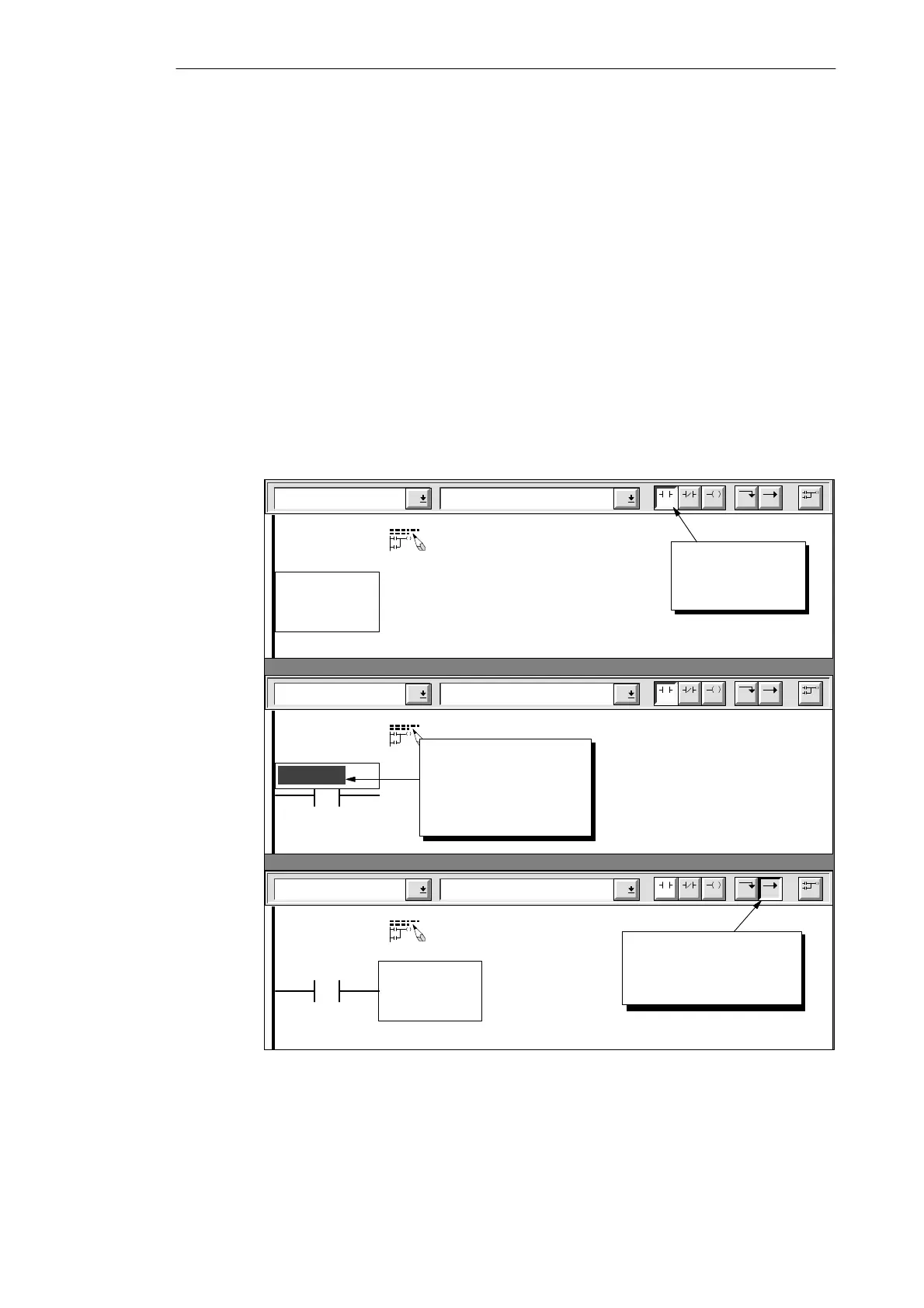
Refer to Figure 3-16 and follow these steps to enter the first network of the sample program:
1. Click the mouse cursor in the left-most position below the network title. Enter a normally
open contact by clicking the F4 toolbar button or by selecting “Contacts” from the family
listing and then selecting “Normally Open” from the instruction listing. A normally open
contact appears with the name “Zone_1” highlighted above it. (Every time you enter a
contact, the software displays the default address of I0.0, which in this example is
defined as “Zone_1” in the Symbol Table.)
2. “Panic_Alarm” is the first element required for Network 1. While “Zone_1” is highlighted,
type either the symbol name Panic_Alarm or the absolute address I0.3 (the software
accepts entry of either form).
3. Press ENTER to confirm the first element. The symbol name “Panic_Alarm” is displayed.
The ladder cursor moves to the second column position.
4. Click the F8 toolbar button to insert a horizontal line. (You can also select “Lines” from the
family listing and then select “Horizontal” from the instruction listing.)
To change or replace one of the elements, move the cursor to that element and select the
new element. You can also cut, copy, or paste elements at the cursor location.
Contacts Normally Open
Network 1
F4 F5 F8F7F6 F10
F3F2
Sound the alarm!
Click the toolbar
button to place
element.
Contacts Normally Open
Network 1
F4 F5 F8F7F6 F10
F3F2
Sound the alarm!
“Zone_1”
Contacts Normally Open
Network 1
F4 F5 F8F7F6 F10
F3F2
Sound the alarm!
“Panic_Alarm”
Click the toolbar button
to insert a horizontal line
segment.
Enter the address:
I0.3
or
Panic_Alarm
Figure 3-16 Entering the First Contact of the First Network
Getting Started with a Sample Program

 Loading...


