3-17
S7-200 Programmable Controller, CPU 210
C79000-G7076-C235-01
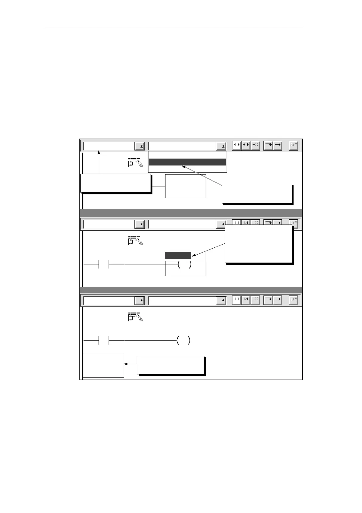
Refer to Figure 3-17 and follow these steps to enter the output coil that ends the first rung of
the first network:
1. Select “Output Coils” from the family listing and select “Set” from the instruction listing.
2. Type either the symbolic name Alarm_Bit or the absolute address M0.1 in the
highlighted area.
3. Pressing ENTER highlights the “number of points” field (located underneath the output
coil). Press ENTER to accept the default value of 1. (The CPU 210 allows only one point
to be set or reset by any one Set or Reset instruction.)
4. Move the cursor to the position below the first contact.
Output Coils Set
Network 1
F4 F5 F8F7F6 F10
F3F2
Sound the alarm!
“Panic_Alarm”
Reset
Output
Set
Output Coils Set
Network 1
F4 F5 F8F7F6 F10
F3F2
Sound the alarm!
“Panic_Alarm”
S
1
Q0.0
Enter the address:
M0.1
or
Alarm_Bit
Output Coils Set
Network 1
F4 F5 F8F7F6 F10
F3F2
Sound the alarm!
“Panic_Alarm”
S
1
“Alarm_Bit”
Position the cursor
below the first contact.
Select “Output Coils”
from the family listing.
Select “Set” from the
instruction listing.
Figure 3-17 Entering the Output Coil
Getting Started with a Sample Program

 Loading...


