3-19
S7-200 Programmable Controller, CPU 210
C79000-G7076-C235-01
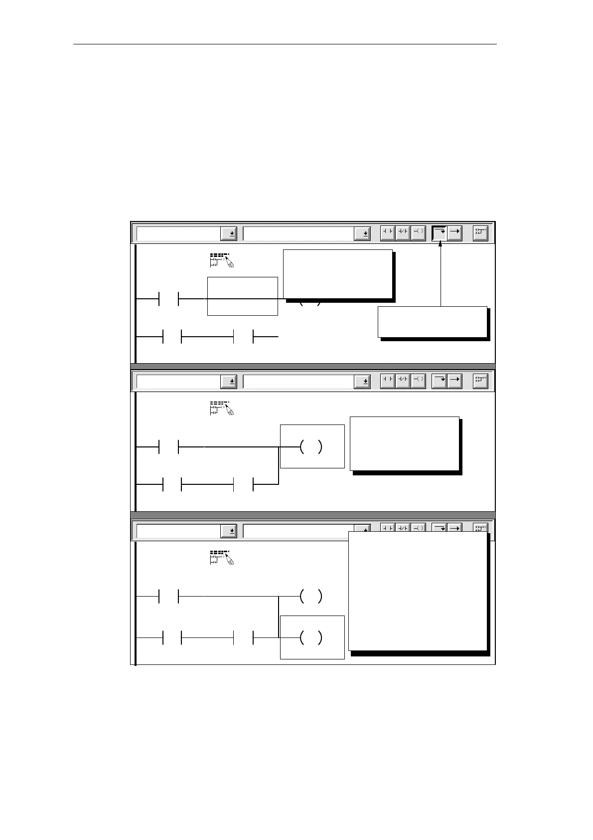
Refer to Figure 3-19 and follow these steps to enter a vertical line and to copy the output coil
from the first rung:
1. Move the cursor to the horizontal line above the contact for “Armed” (or I0.2). Click the
F7 toolbar button to insert a vertical line that connects the first rung with the second rung.
2. Move the cursor to the output coil on the first rung. Use the menu command Edit
"
Copy
to copy the output coil to the clipboard.
3. Move the cursor down and use the menu command Edit
"
Paste to paste the output
coil. Type Modem (or Q0.3) in the highlighted field and press ENTER. Press ENTER
again to accept the default value of 1.
Lines Vertical
Network 1
F4 F5 F8F7F6 F10
F3F2
Sound the alarm!
“Panic_Alarm”
S
1
“Alarm_Bit”
>=I
+600
“Alert_Timer”
“Armed”
Click the toolbar button
to insert a vertical line.
Output Coils Set
Network 1
F4 F5 F8F7F6 F10
F3F2
Sound the alarm!
“Panic_Alarm”
S
1
“Alarm_Bit”
>=I
+600
“Alert_Timer”
“Armed”
Copy the Set instruction
by selecting the
Copy command from
the Edit menu.
Output Coils Set
Network 1
F4 F5 F8F7F6 F10
F3F2
Sound the alarm!
“Panic_Alarm”
S
1
“Alarm_Bit”
>=I
+600
“Alert_Timer”
“Armed”
Move the cursor vertically and
paste the instruction at the
cursor location. Use the
Paste command from the Edit
menu.
Enter the address (Q0.3
or
Modem) and press ENTER.
Press ENTER again to accept
the value (1).
S
1
“Modem”
Position the cursor on
the top rung of the
network.
Figure 3-19 Entering a Vertical Line and Copying the Output Coil
Getting Started with a Sample Program

 Loading...


