3-20
S7-200 Programmable Controller, CPU 210
C79000-G7076-C235-01
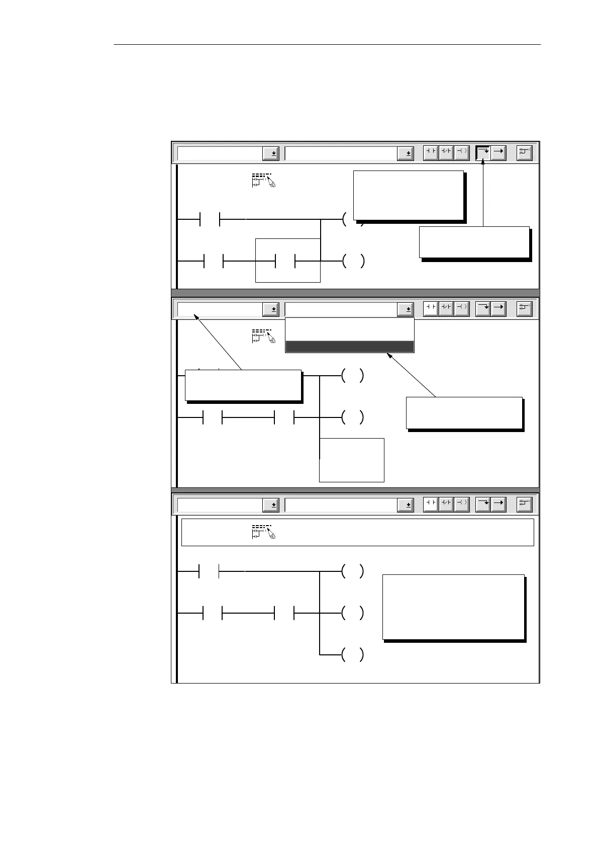
Figure 3-20 shows the remaining steps for finishing the first network. After you have entered
the first network, move the cursor to the second network. Refer to Figure 3-11 and enter the
remaining networks of the sample program.
Lines Vertical
Network 1
F4 F5 F8F7F6 F10
F3F2
Sound the alarm!
“Panic_Alarm”
S
1
“Alarm_Bit”
>=I
+600
“Alert_Timer”
“Armed”
S
1
“Modem”
Click the toolbar button
to insert a vertical line.
Output Coils Reset
Network 1
F4 F5 F8F7F6 F10
F3F2
“Panic_Alarm”
S
1
“Alarm_Bit”
>=I
+600
“Alert_Timer”
“Armed”
S
1
“Modem”
Sound the alarm!
>= Integer
Select “Reset” from the
instruction listing.
Output
Set
Reset
Output Coils Reset
Network 1
F4 F5 F8F7F6 F10
F3F2
“Panic_Alarm”
S
1
“Alarm_Bit”
>=I
+600
“Alert_Timer”
“Armed”
S
1
“Modem”
Sound the alarm!
>= Integer
Enter the address (M0.2
or
Low_Bit) and the value (1).
The first network is now
complete.
R
1
“Low_Bit”
Select “Output Coils”
from the family listing.
Position the cursor over
the contact for “Armed”
(
or
I0.2).
Figure 3-20 Completing the First Network
Getting Started with a Sample Program

 Loading...


