Installing the S7-400
2-15
Automation System S7-400 Hardware and Installation
A5E00850741-01
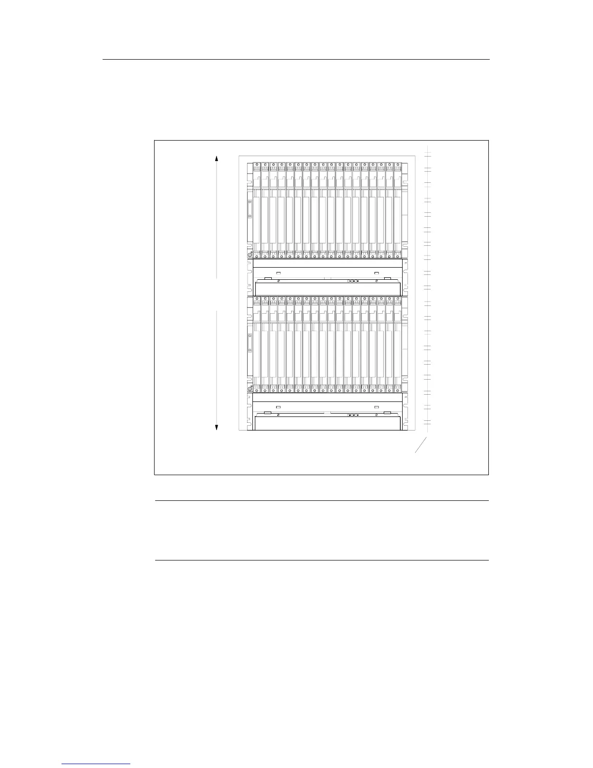
The figure below shows how much space you must allow for when assembling an
S7-400 from two racks with a cable duct or fan subassembly. This requirement is
increased by a height of 400 mm for each additional rack with a cable duct or fan
subassembly.
Mounting depth, fitted: max. 237 mm
840 mm
19-inch reference level
Cable duct/fan subassembly
Cable duct/fan subassembly
1 2 3 4 5 6 7 8 9 101112131415161718
1 2 3 4 5 6 7 8 9 10 11 12 13 14 15 16 17 18
Note
A minimum clearance as shown in the above figure between rack and cable duct
or fan subassembly must not be provided, but is essential between two adjacent
racks and between racks and other equipment.

 Loading...


