Safety
Fail-Safe Systems
7-6 A5E00085588-03
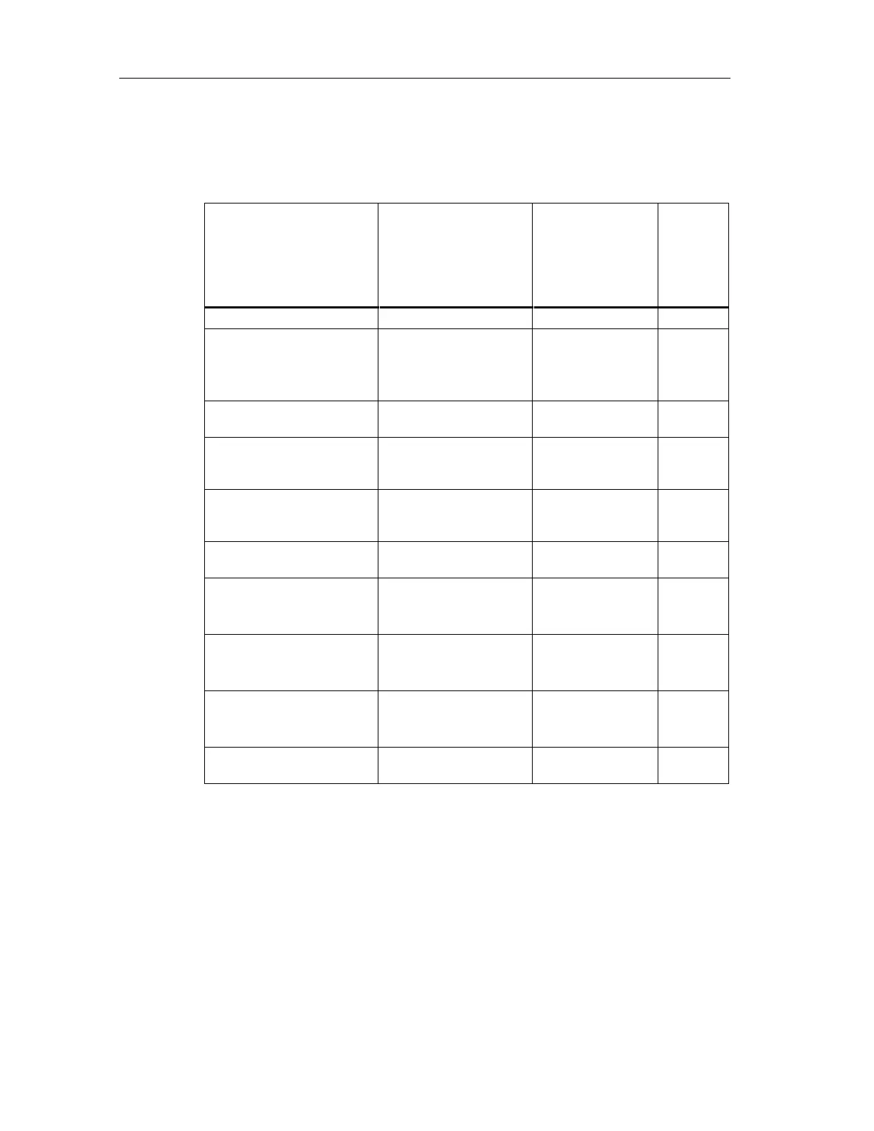
The following table lists the probability values of individual components of the S7
F/FH Systems:
Low Demand Mode of
Operation
(Average probability of
failure to perform its
design function on
demand)
High Demand or
Continuous Mode
of Operation
(Probability of a
dangerous failure
per hour)
Proof test
interval
F-capable CPU 1,24E-04 1,42E-09 10 years
SM 326; DO 10 x DC
24V/2A; with diagnostic
interrupt
6ES7 326-2BF00-0AB0
6,97E-06 7,96E-11 10 years
ET 200S PM-E F 24 VDC
PROFIsafe Power Module
<< 1.00 E-05 << 1.00 E-10 10 years
ET 200S EM 4/8 F-DI 24
VDC PROFIsafe Digital
Electronic Module
<<1.00 E-03 at SIL 2
<<1.00 E-05 at SIL 3
<<1.00 E-08 at SIL 2
<<1.00 E-10 at SIL 3
10 years
ET 200S EM 4 F-DO 24
VDC/2 A PROFIsafe Digital
Electronic Module
<<1.00 E-05 <<1.00 E-10 10 years
ET 200S PM-D F 24VDC
PROFIsafe Power Module
<<1.00 E-05 <<1.00 E-10 10 years
SM 326; DI 24 x DC 24V;
with diagnostic interrupt
6ES7 326-1BK00-0AB0
1,55E-06 at SIL 2
4,99E-08 at SIL 3
1,77E-11 at SIL 2
5,70E-13 at SIL 3
10 years
SM 326; DI 8 x NAMUR;
with diagnostic interrupt
6ES7 326-1RF00-0AB0
2,74E-06 at SIL 2
4,83E-08 at SIL 3
3,13E-11 at SIL 2
5,51E-13 at SIL 3
10 years
SM 336; AI 6 x 13Bit;
with diagnostic interrupt
6ES7 336-1HE00-0AB0
4,96E-08 at SIL 3 5,66E-13 at SIL 3 10 years
Safety-related
communication
1,00E-05 1,00E-09
You can obtain the contribution of the S7 F/FH System to the failure probability of a
safety function by adding up the failure probabilities of all the CPUs and F-SMs of
the S7 F/FH System that are involved. Redundant CPUs are counted singly –
redundant F-SMs are counted double. The contribution of safety-related
communication must then be added. Several S7 F/FH Systems can be involved in
a safety function.
 Loading...


