SIMATIC VS710
Quick Reference Guide
12
SIMATIC VS 710
A5E00032597-02
2.5 Digital Input / Output - Connector Pinout
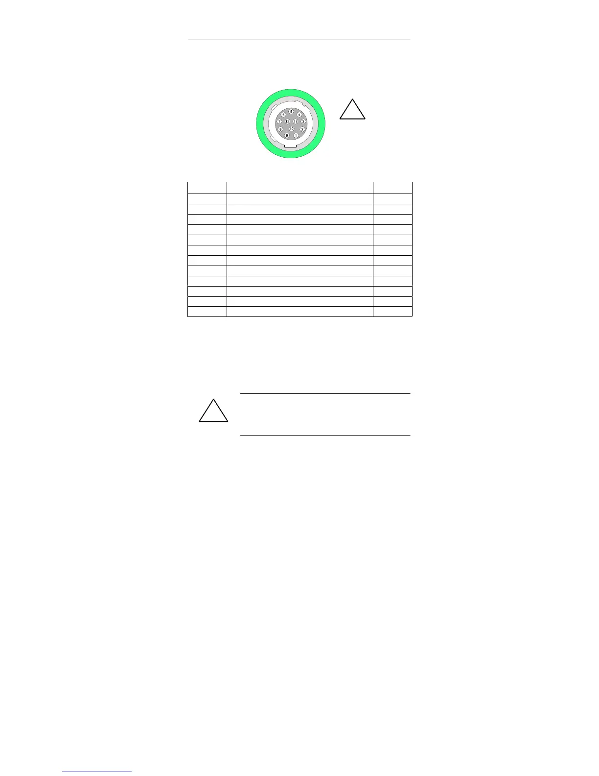
12-pin round plug
Digital I/O
!
Figure 8 Digital Input / Output - Interface
Pin Signal Pin
1 24 volts L+
2 Ground 24 volts M
3 Digital output point 0 DO 0
4 Digital output point 1 DO 1
5 Digital output point 2 DO 2
6 Digital output point 3
1)
DO 3
7 Digital input point 0
2)
DI 0
8 Not assigned
9 Not assigned
10 24 volts L+
11 Ground 24 volts M
12 Digital input point 1
2)
DI 1
1
Simultaneous flash signal under ProVision
2
Triggering interrupt
• Maximum cable length 10 m, shielded
• 2 input points, optically isolated. All input points are referenced to a
common ground. Rated voltage: DC 24V
• 4 output points, optically isolated. All output points are referenced to a
common ground. Output current: 0.5 A. Rated load voltage DC 24 V
• Maximum current per pin = 1 A.
!
Warning
DI and D0 are galvanically coupled by ground pins 2 and 11.
DI 2x 24 VDC
DO 4x 24 VDC/0.5 A, P.D./RES, 5 W tungsten