SIMATIC VS710Quick Reference Guide
SIMATIC VS 710
A5E00032597-02
15
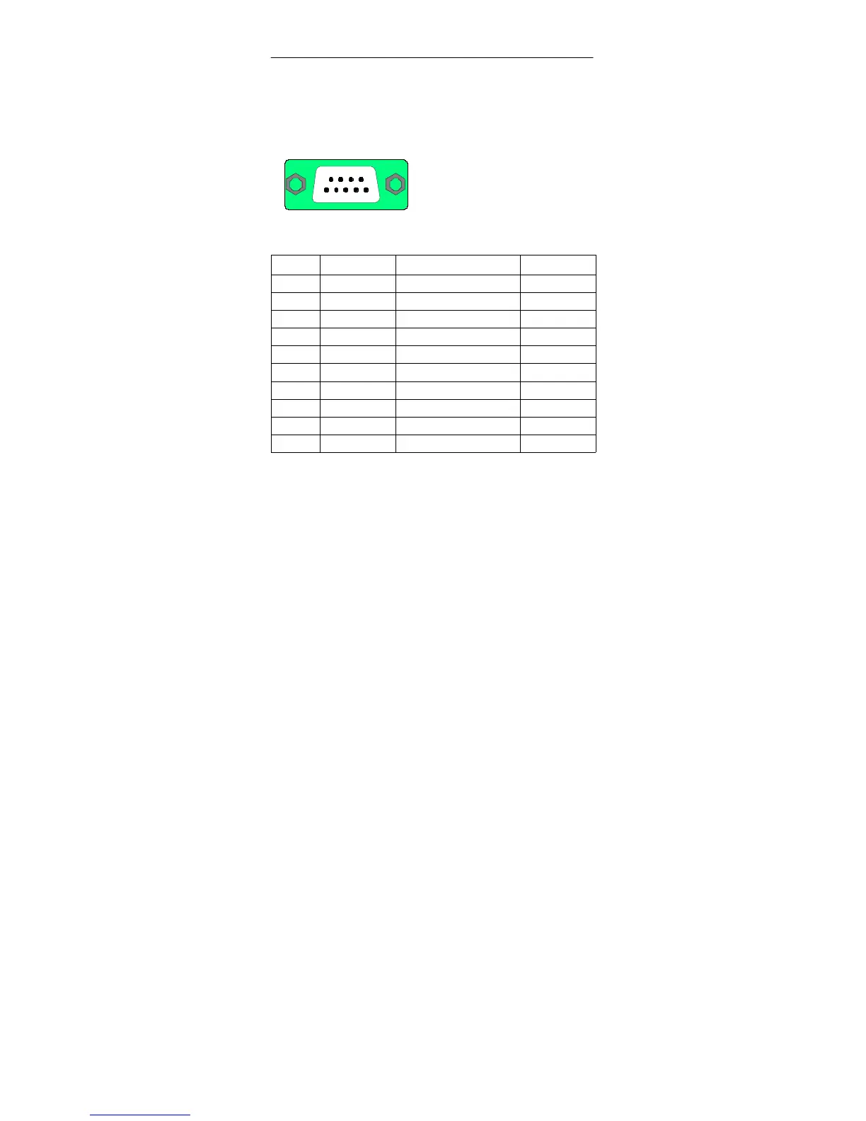
2.6 DP Connector Pinout
54321
9876
9-pin subminiature D connector
Figure 13 DP Interface
Pin Signal Function Input/Output
1 Not assigned - -
2 Not assigned - -
3 LTG_B Signal line B Input/output
4 RTSAS Request to send (PLC)
1
) Output
5 M5
ext
GND (isolated)
2
) Output
6 P5
ext
+5V (isolated)
3
) Output
7 Not assigned
8 LTG_A Signal line A Output
9 Not assigned - -
Shield On connector casing
1
) Control signal for received data flow
The control is “1” active when the programmable controller is sending
2
) 0 V line of the 5 V power supply
3
)P5
ext
power supply (+5 V) of the 5 V power supply (powers bus
terminator)
The DP interface operates on the slave principle and is designed as a
floating interface. It has a maximum data transfer rate of 12 Mbps.
When using a point-to-point connection with a transmission rate of
12 Mbps, a line length of 100 m may be used.