Description of system components
8.14 Configuration information for SIMOCODE pro V when using an older basic unit
SIMOCODE pro
156 System Manual, 05/2019, A5E40507475002A/RS-AD/004
Maximum configuration with expansion modules
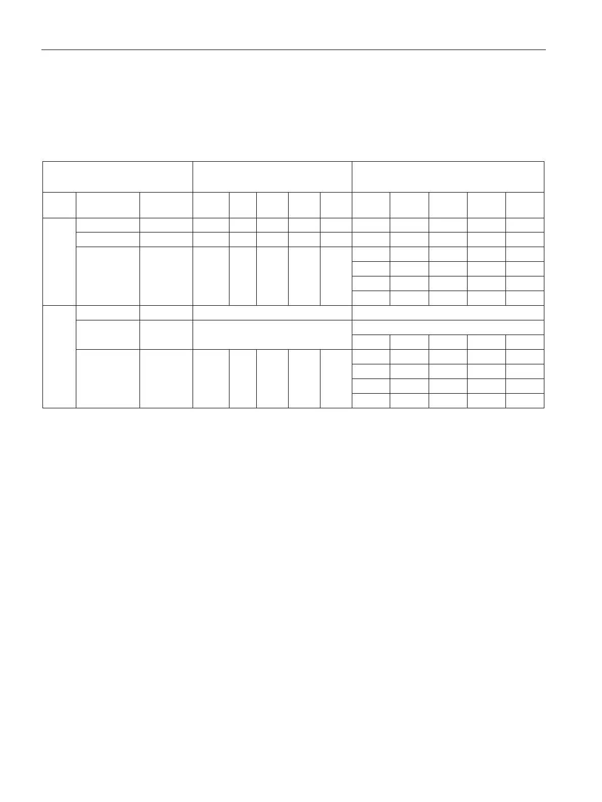
Table 8- 7 Maximum configuration with expansion modules when using an operator panel/operator panel with display, a
1st generation current/voltage measuring module and a decoupling module for SIMOCODE pro V PB basic
units (3UF7010-1A.00-0) with a 24 V DC or 110 V - 240 V AC/DC supply
SIMOCODE pro basic unit
U
s
= 24 V DC
SIMOCODE pro basic unit
U
s
= 110-240 V AC/DC
OP Measurement Decoupling
DM-F/
DM AM TM EM DM-F/
DM AM TM EM
None/
OP
U/I
4)
✓ ✓
1)
✓
1)
✓ ✓ ✓ ✓ ✓ - ✓ ✓
1)
1)
OPD
U/I - Max. 4 modules
5)
U/I
4)
✓ ✓
✓
-
✓
✓
-
✓
✓
✓
✓
2)
1)
1)
3)
1) No bistable relay outputs and no more than 5 of 7 relay outputs active simultaneously
(> 3 s)
2) No bistable relay outputs and no more than 3 of 5 relay outputs active simultaneously
(> 3 s)
3) Analog module output is not used.
4) 1st generation current/voltage measuring modules; MLFB ending in 000
(e.g. 3UF7110-1AA00-0)
5) AM and TM cannot be used at the same time