Mounting, wiring, connecting, system interfaces, configuration guidelines
12.2 Wiring, connecting
SIMOCODE pro
214 System Manual, 05/2019, A5E40507475002A/RS-AD/004
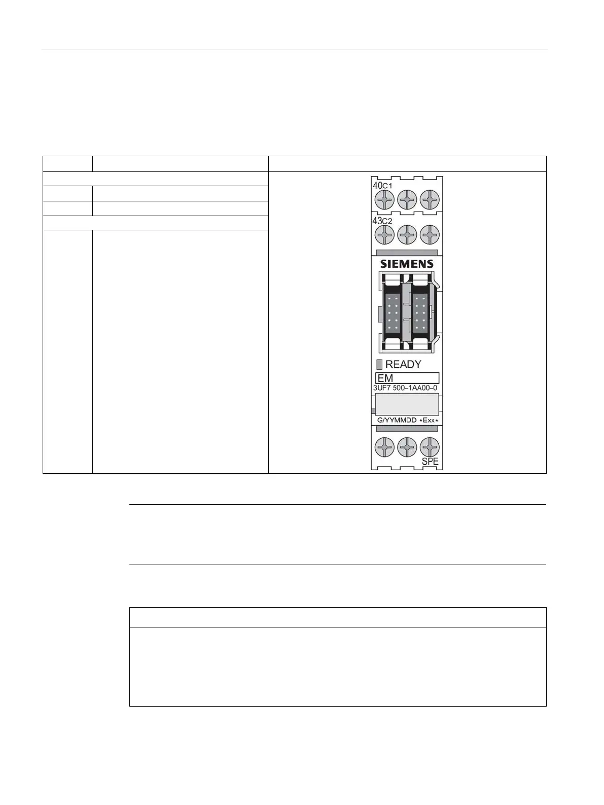
Terminal assignment of the ground-fault module
The following table shows the assignment of the removable terminals:
Table 12- 14 Terminal assignment of the removable terminals of the ground-fault module
40 Input C1 residual current transformer
Input C2 residual current transformer
SPE
1)
System shielding
1)
pro via terminal SPE with the maximum possible cross-section and
s short a cable as possible to the functional ground of the control cabinet,
e.g. to the grounded mounting plate of the control cabinet.
Types of ground-fault module
The 3UF7 500-1AA00-0 ground-fault module requires the 3UL22 residual current
transformer.
The 3UF7 510-1AA00-0 ground-fault module requires the 3UL23 residual current
transformer.