Blocking Protection for Pumps with SIMOCODE pro V
Article ID: 109478058, V2.0, 09/2020
© Siemens AG
2020 All rights reserved
The function plan in Figure 2-1, which is referenced by the following models, only
shows the supplementary logic for blockage prevention (hereafter referred to
shorthand as "logic"). The standard interconnections for the underlying reversing
starter are not part of Figure 2-1.
2.1 Logic blocks in use
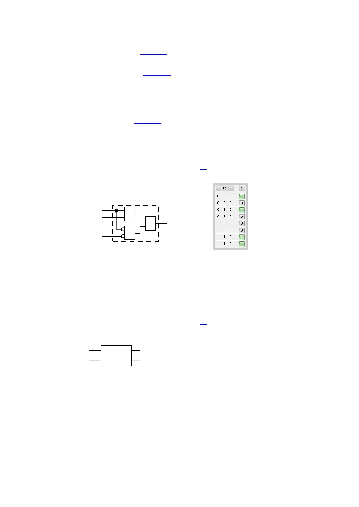
Truth table
A logical linkage of digital signals can be implemented with a truth table. For ease
of understanding, Figure 2-1 shows the truth tables as gates or a combination of
gates. Truth tables with the following input/output quantity structures are available:
• "3I/1O"
• "2I/1O"
• "5I/2O"
Detailed information is available in manual \3\.
Figure 2-2
Counters
For every positive edge at one of the counter inputs (+/-), the counter value is
incremented or decremented. The application example only uses the "+" counter
inputs. If the defined limit value is reached, e.g. 4 for Counter 1, the output (Q)
switches to "true". The counter can be reset to 0 with the reset input (R). The
counter value is available as an output.
Detailed information is available in manual \3\.
Figure 2-3