Blocking Protection for Pumps with SIMOCODE pro V
Article ID: 109478058, V2.0, 09/2020
© Siemens AG
2020 All rights reserved
2. For the commands "ON>", "OFF" and "ON<", create the following three control
elements as per the image above:
– "Local control":
Inputs 1-3 of the SIMOCODE pro V PN basic unit (BU inputs)
Reverse direction
"ON<" (input 1)
"OFF"
(input 2)
Forward direction
"ON>" (BU input 3)
Unrestricted
– "PLC/DCS":
Bits 0.0-0.2 of the cyclic communication "Cyclic receive Byte 0"
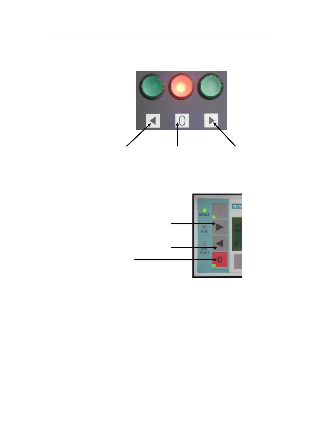
– "Operator panel": Buttons 2-4 (OP buttons)
Forward direction "ON>" (key 2)
Reverse direction "ON<" (key 3)
"OFF" (key 4)
3. Switch to "Motor control > Control function".
4. Enable the operating mode "Save change-over command".
5. Interconnect the control commands "ON<" and "ON>" with the outputs of the
relevant truth tables.
– "ON<": TT 7 (truth table 7)
– "ON>": TT 2 (truth table 2)
6. For "Timings", set the interlocking time needed for your application. Using the
2 s set in the example, the switch-on interlock can be easily observed in the
event of a reversal.