Configuration
5.2 Procedure when engineering
S-1FT7 synchronous motors
Configuration Manual, 09/2018, A5E45099423B AA
115
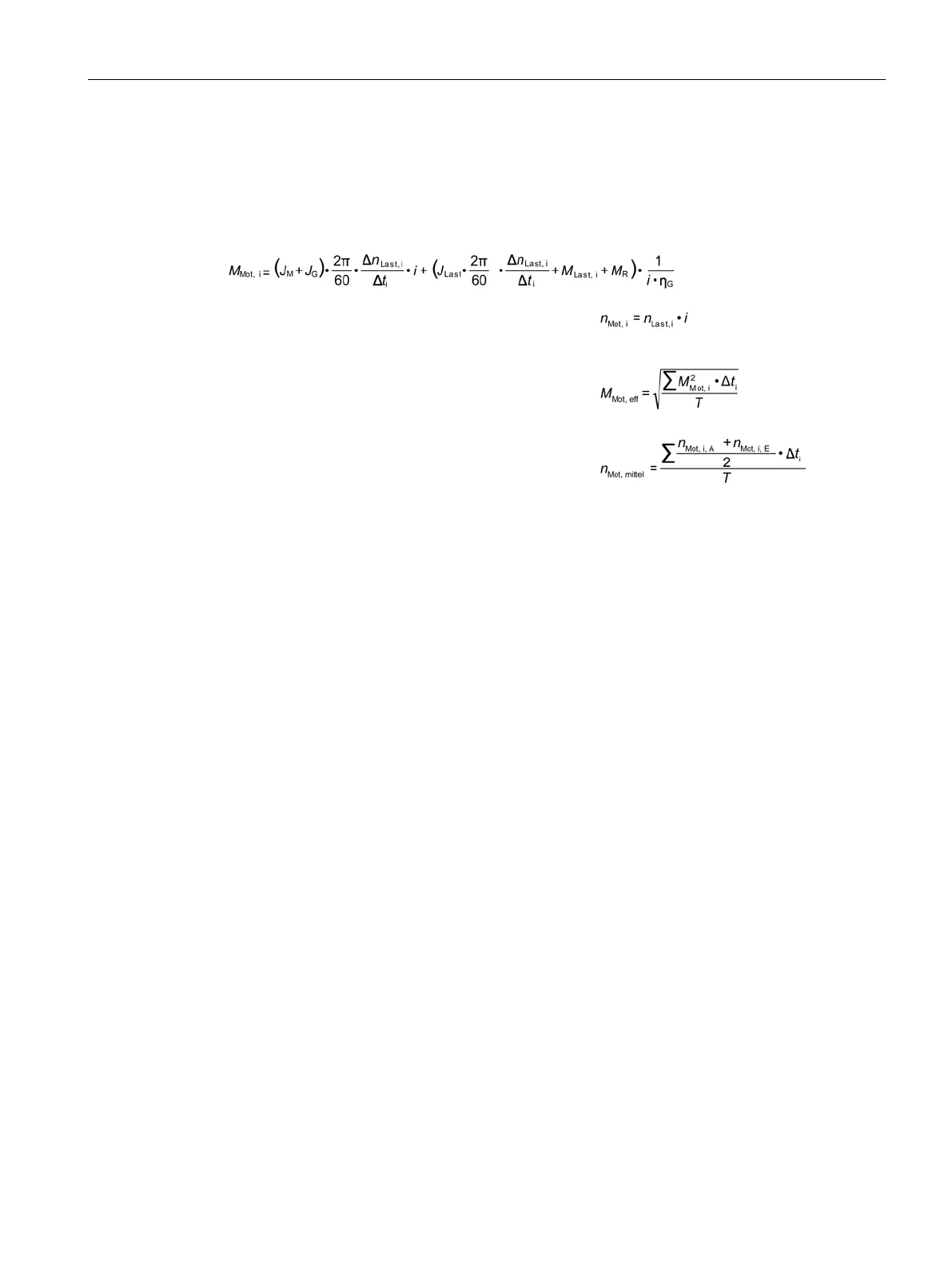
The following formulas can be used for duty cycles outside the field weakening range. For
duty cycles in the field weakening range, the drive system must be configured using the
SIZER configuration tool.
For the motor torque in a time slice Δ
t
i
the following applies:
e torque is obtained as follows:
The average motor speed is calculated as follows:
G
Gearbox moment of inertia
load
load
load
R
Initial value, final value in time slice Δ
t
i
i
The effective torque M
eff
must lie below the S1 characteristic curve.
The maximum torque M
max
is produced during the acceleration operation. M
max
must lie
below the voltage limiting characteristic curve. In summary, the motor is configured as
follows: