Configuration
5.2 Procedure when engineering
S-1FT7 synchronous motors
116 Configuration Manual, 09/2018, A5E45099423B AA
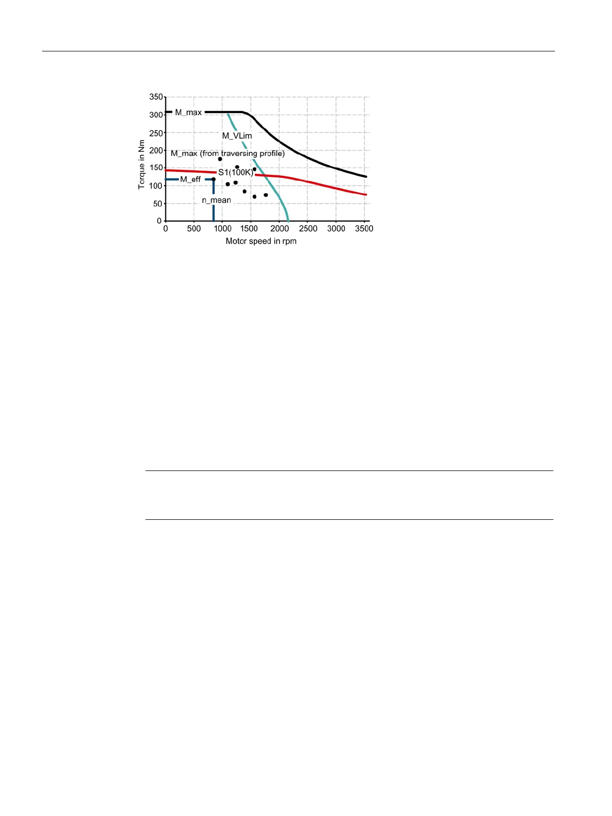
M_max
Curve of the maximum
S1 (100K) S1 characteristic curve for 100 K = M
0
Points from the traversing profile
Voltage limiting characteristic curve
Figure 5-6 Motor selection for duty cycle (example)
You have defined the characteristic motor values corresponding to the duty cycle.
❒
Specification of the motor
By varying, you can find the motor that satisfies the conditions of the operating mode (duty
cycle).
● Determine the motor current at base load. The calculation depends on the type of motor
(synchronous motor or induction motor) and the operating mode (duty cycle) used.
Note
When configuring according to duty cycle with constant ON duration with overload, the
overload current is calculated in relation to the required overload torque.
● Comply with the thermal limits of the motor.
● Configure the other properties of the motor through the available motor options.