Technical data and characteristic curves
6.1 Explanations
S-1FT7 synchronous motors
134 Configuration Manual, 09/2018, A5E45099423B AA
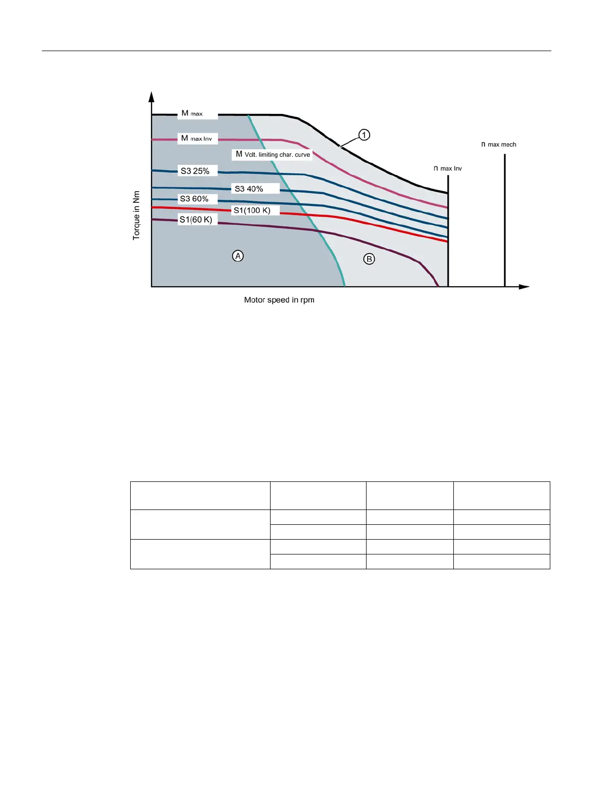
Voltage limit characteristic without field weakening
Voltage limit characteristic with field weakening
Figure 6-2 Shape of the voltage limiting characteristic with/without field weakening
The characteristics for each winding version are shown in a separate data sheet.
The torque-speed diagrams for different converter output voltages are assigned to each data
sheet:
Table 6- 1 Converter output voltages
Converter output
voltage V
mot
Upper diagram
Lower diagram 460 V SINAMICS SLM 480 V
For different converter output voltages, the voltage limiting characteristic curve must be
offset accordingly. See "Explanations (Page 131)"
Torque limit when operating on a SINAMICS S120 drive system without field weakening
It is possible to deactivate the field weakening function with the SINAMICS S120 drive
system. This therefore reduces the operating range that is available.
In the diagram "Torque characteristics of synchronous motors" below, the area without field
weakening is marked with "A".
The voltage induced in the motor winding increases as the speed increases.