Technical data and characteristic curves
6.1 Explanations
S-1FT7 synchronous motors
Configuration Manual, 09/2018, A5E45099423B AA
135
The difference between the DC link voltage of the converter and the induced motor voltage
can be used to impress the current. This difference limits the applicable current level. This
causes the torque to drop off quickly at high speeds.
All operating points that can be achieved with the motor lie to the left of the voltage limiting
characteristic line in area "A".
The characteristics for each winding version are shown in a separate data sheet. The torque-
speed diagrams for different converter output voltages are assigned to each data sheet:
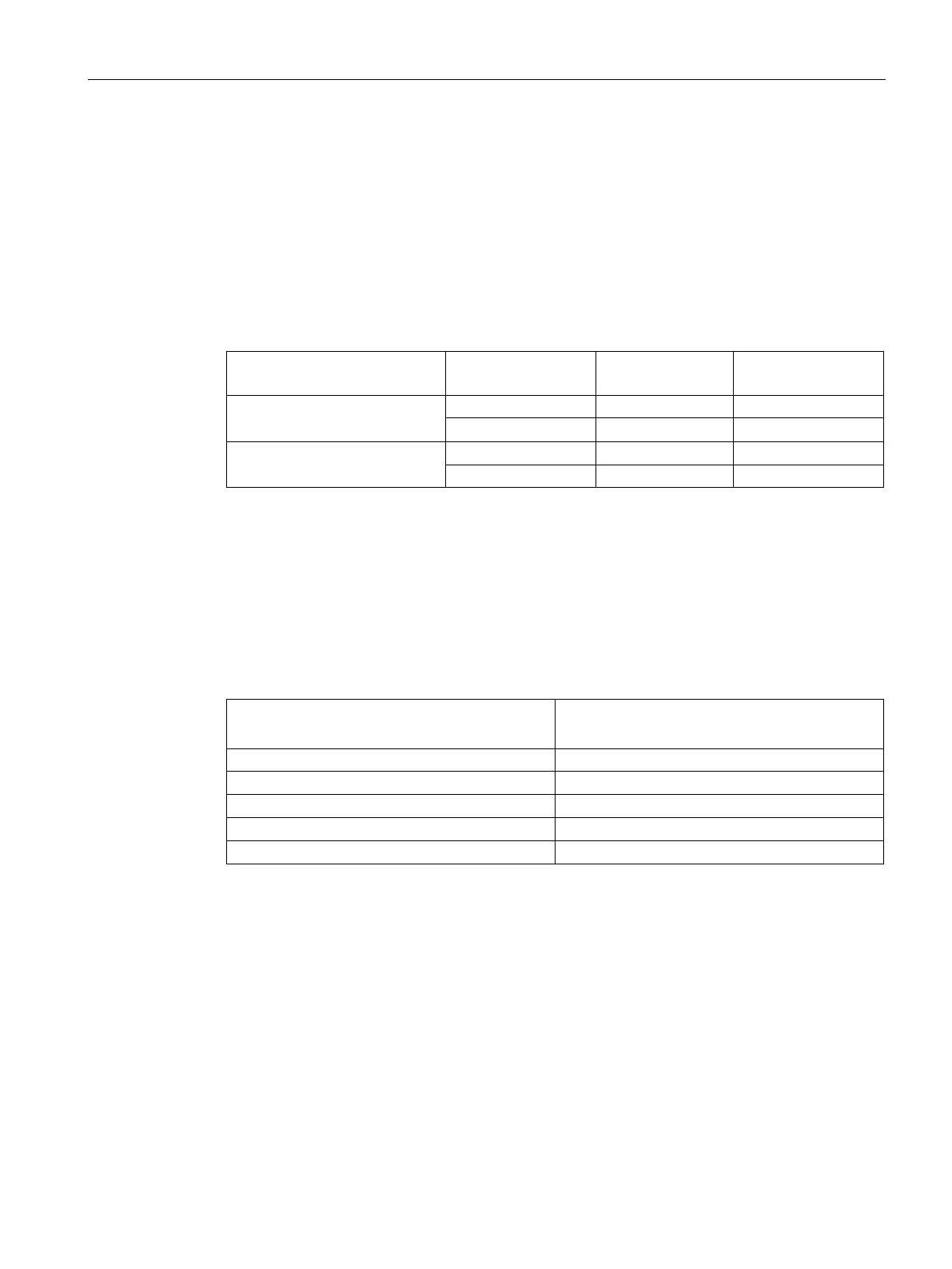
Table 6- 2 Converter output voltages
Converter output
voltage V
mot
Upper diagram
425 V SINAMICS ALM 400 V
Lower diagram
510 V SINAMICS ALM 480 V
For different converter output voltages, the voltage limiting characteristic curve must be
offset accordingly. See "Explanations (Page 131)."
Several winding types (armature circuits) for different rated speeds n
N
are possible within
one motor frame size.
Table 6- 3 Code letter, winding type
Winding type
(10th digit of the order no.)