Electrical connection
8.3 System integration
S-1FT7 synchronous motors
Configuration Manual, 09/2018, A5E45099423B AA
371
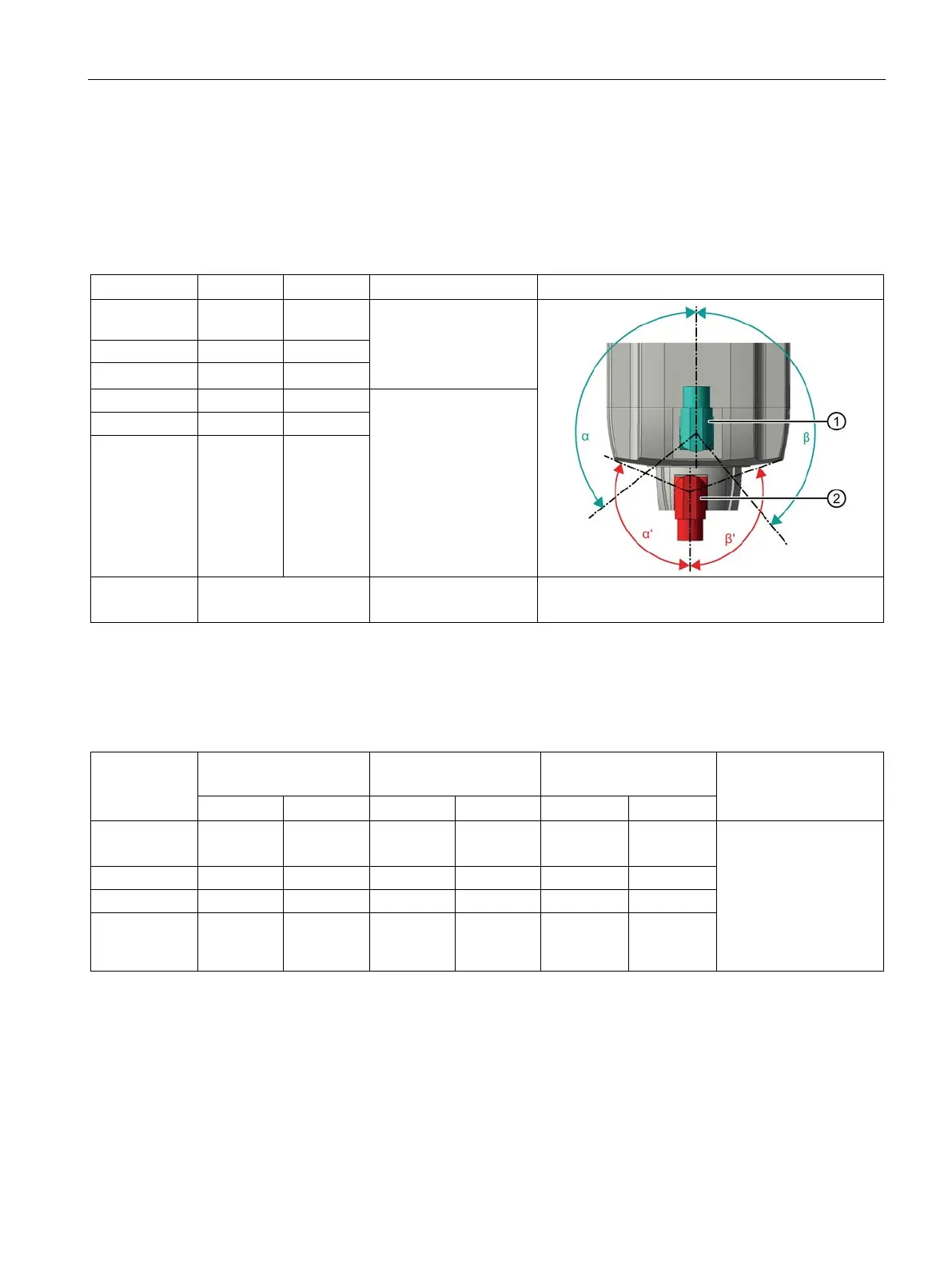
Ability to rotate the connector on motors with natural cooling/water cooling without DRIVE-CLiQ
interface (M23 round connector) and on motors with DRIVE-CLiQ interface via Sensor Modules or
M17 round connector
1FT7□□□-□A□□□-□X□□, 1FT7□□□-□W□□□-□X□□; X = K, L, M, N, D, F
Table 8- 4 Rotation range of the power connector ①
1FT703☐
115 ° 145 °
M23
1FT708☐ 130 ° 150 °
M40
1FT708☐
1FT710☐
1FT713☐
190 ° 135 °
1FT7117
cannot be rotated M58
Figure power connector, connector size M23
② Figure signal connector, round connector M17
Table 8- 5 Rotation range of the signal connector ②
with DRIVE-CLiQ via
Sensor Module
1FT703☐
145 ° 120 ° 145 ° 120 ° 125 ° 130 ° See table "Rotation
range of the power
connector (without
DRIVE-CLiQ)"
1FT710☐
1FT7117
95 ° 95 ° 95 ° 95 ° 95 ° 95 °