Electrical connection
8.3 System integration
S-1FT7 synchronous motors
372 Configuration Manual, 09/2018, A5E45099423B AA
Ability to rotate the power connectors for the motor and the fan for motors with forced ventilation
1FT7□□□-□S□□□-□□□□
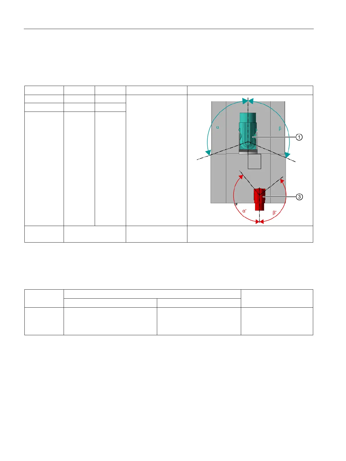
Table 8- 6 Rotation range of the power connector for the motor ①
M40
1FT708☐ 110 ° 110 °
1FT710☐ 185 ° 135 °
1FT7117
cannot be rotated M58
Figure power connector, connector size M40
③ Figure power connector of fan, connector size M23
Table 8- 7 Ability to rotate the signal connector (not visible, under the fan cover or in the intermediate flange) ②
with DRIVE-CLiQ via Sensor Modules, M23 or M17 connector
1FT706☐
1FT708☐
1FT710☐
Only 90° fixed adjustable
1)
Only 90° fixed adjustable
1)
See table "Rotation range of
the power connector (for
natural cooling/water cool-
1) For other angles, the signal cable can come into contact with the fan and so be damaged.