Electrical connection
8.3 System integration
S-1FT7 synchronous motors
Configuration Manual, 09/2018, A5E45099423B AA
373
Table 8- 8 Rotation range of the power connector for the fan ③
1FT706
1FT708
155 ° 130 ° See table "Rotation range of the power
connector for the motor"
1FT7117
1FT713☐
with power connector size M58 75 ° 60 °
Table 8- 9 Max. torque when rotating
Max. torque when rotating
Selectable outlet directions of the fixed connectors for motor and fan
The outlet directions apply for naturally cooled and force-ventilated motors
Table 8- 10 Fixed connector for motor and fan
1FT7117
M58 M23
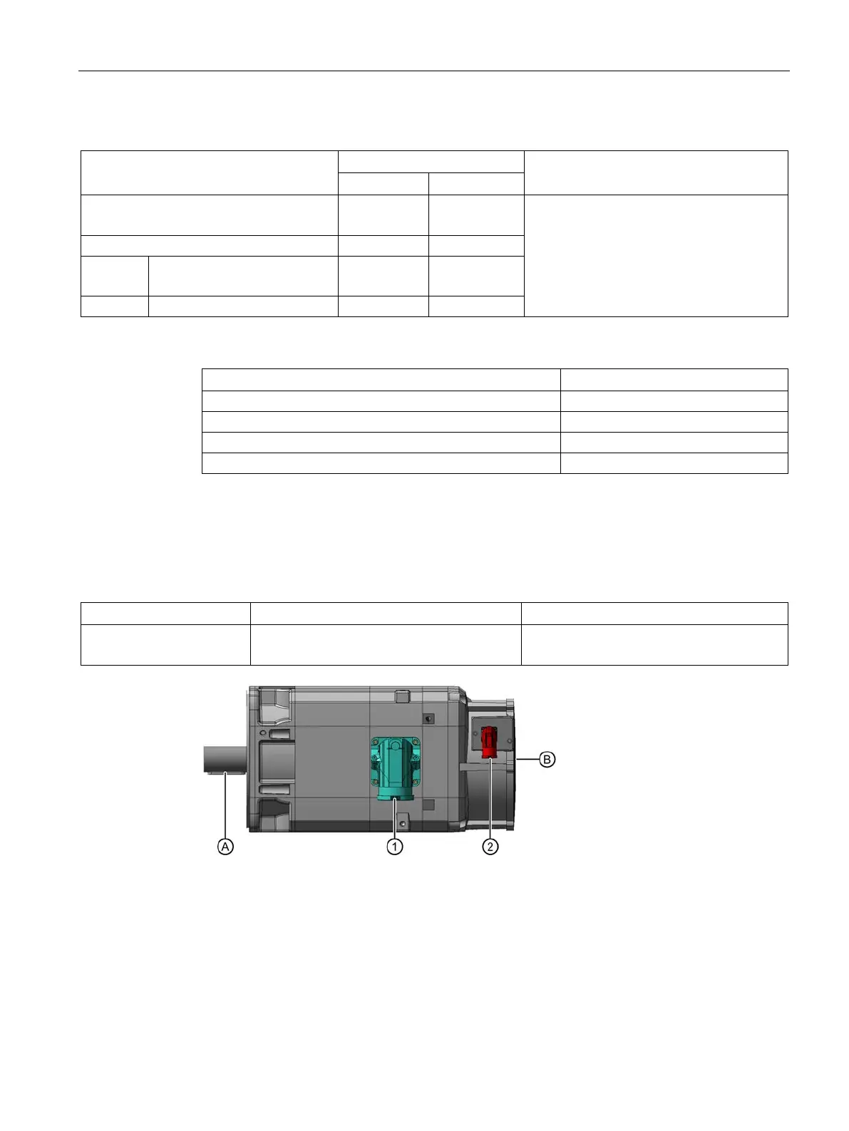
Power connector, example shows Q41
Fan connector, example shows Q41
Figure 8-2 Outlet direction of the fixed connectors
Table 8- 11 Outlet directions of the fixed connectors