EasyManuals Logo

Siemens SIMOTICS S-1FT7 User Manual

Siemens SIMOTICS S-1FT7
408 pages
To Next Page IconTo Next Page
To Previous Page IconTo Previous Page
Page #384 background imageLoading...
Page #384 background image
Electrical connection
8.3 System integration
S-1FT7 synchronous motors
382 Configuration Manual, 09/2018, A5E45099423B AA
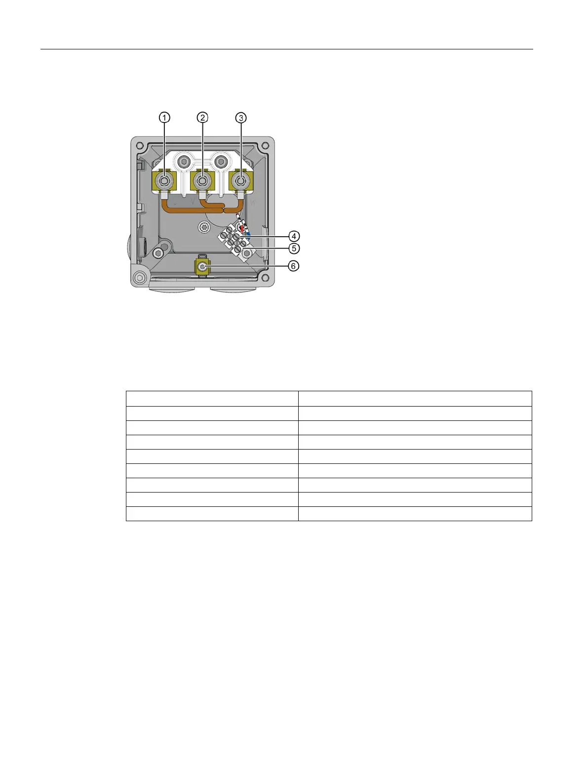
Terminal diagram terminal box GK 230
1, 2, 3
Main terminals U, V, W
4, 5
Brake connection (optional), 4 = BD1+, 5 = BD2-
6
Ground connection
Figure 8-5 Terminal box GK 230
Table 8- 12 Terminals for the terminal box GK 230
Terminal box type
GK 230
Cable entry
1 x PG 29 / 1 x PG 9
Max. outer cable diameter
1)
30 mm
RMS current per terminal
2)
66 A
Number of main terminals U, V, W
3 x M5
Max. cross-section per terminal
1 x 16 mm
2
Ground connection
M4
Tightening torque [Nm]
0.8 - 1.2
Brake connection
3)
1.5 mm
2
1)
Depends on the seal used
2)
Data according to DIN EN 60204-1 (installation type C, ambient temperature 40 °C)
3)
BD1+/BD2- (terminal strip, only for versions with brake)

Table of Contents

Questions and Answers:

Question and Answer IconNeed help?

Do you have a question about the Siemens SIMOTICS S-1FT7 and is the answer not in the manual?

Siemens SIMOTICS S-1FT7 Specifications

General IconGeneral
BrandSiemens
ModelSIMOTICS S-1FT7
CategoryEngine
LanguageEnglish

Related product manuals