Electrical connection
8.3 System integration
S-1FT7 synchronous motors
Configuration Manual, 09/2018, A5E45099423B AA
385
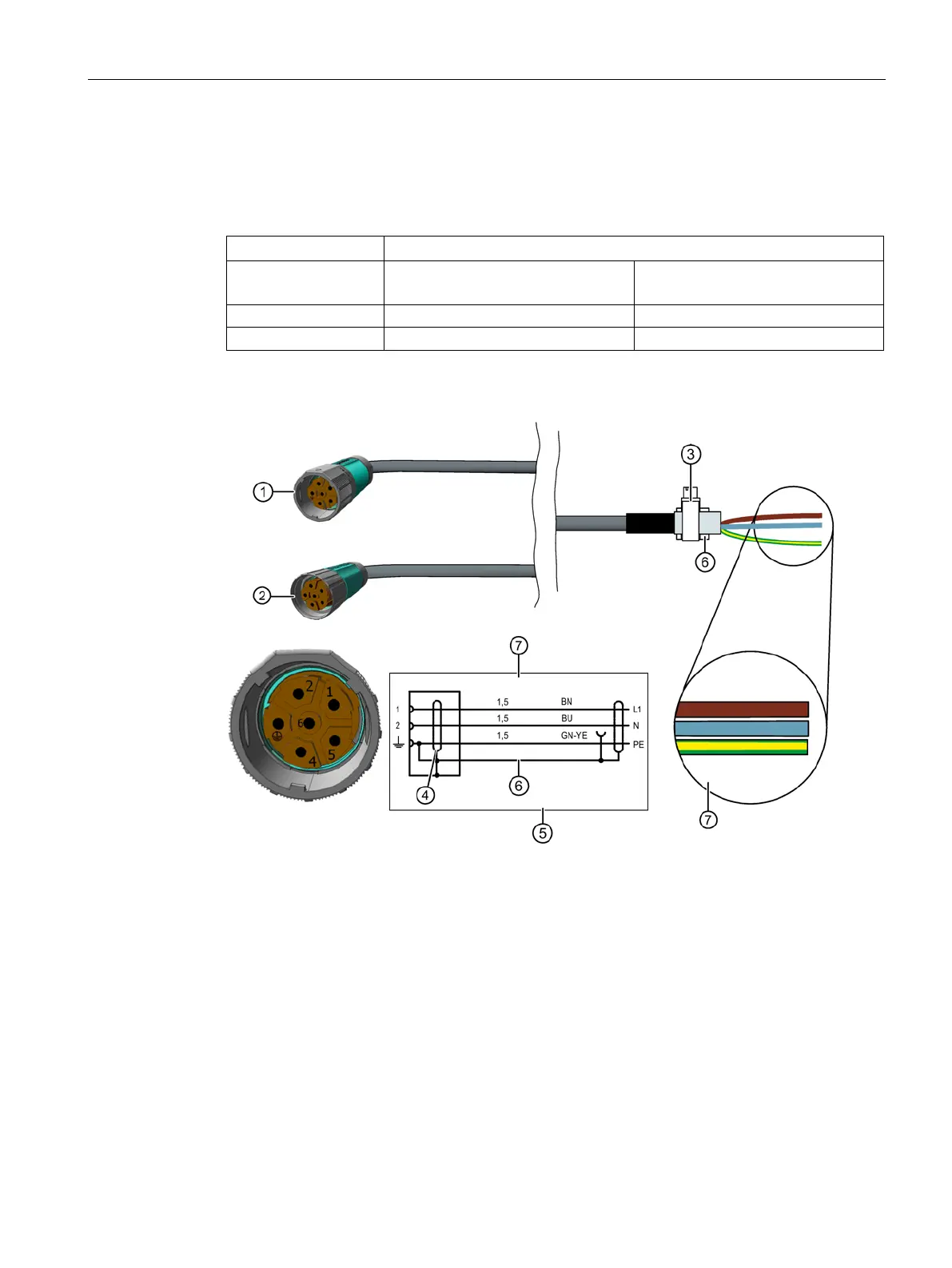
Connection of a 1-phase separately driven fan
Table 8- 14 Connection values for a 1-phase separately driven fan for the 1FT7 up to shaft height
100
Max. current consumption at
230 V / 50 Hz (±10 %)
in A
230 V / 60 Hz (±10 %)
in A
Connector size M23 (with full thread)
Connector SPEED-CONNECT size M23
Terminal for the cable shield
7 Conductor designation:
Power cable, 1.5 mm
2
PE = protective conductor, 1.5 mm²
Figure 8-7 Connecting to a 1-phase separately driven fan