Electrical connection
6.7 Connecting the converter
1LA5/6/7/9, 1LG4/6, 1MA6/7, 1MB..1/2/3/4/5 - SH 63 ... 355
84 Operating Instructions, 06/2018, A5E44455710A
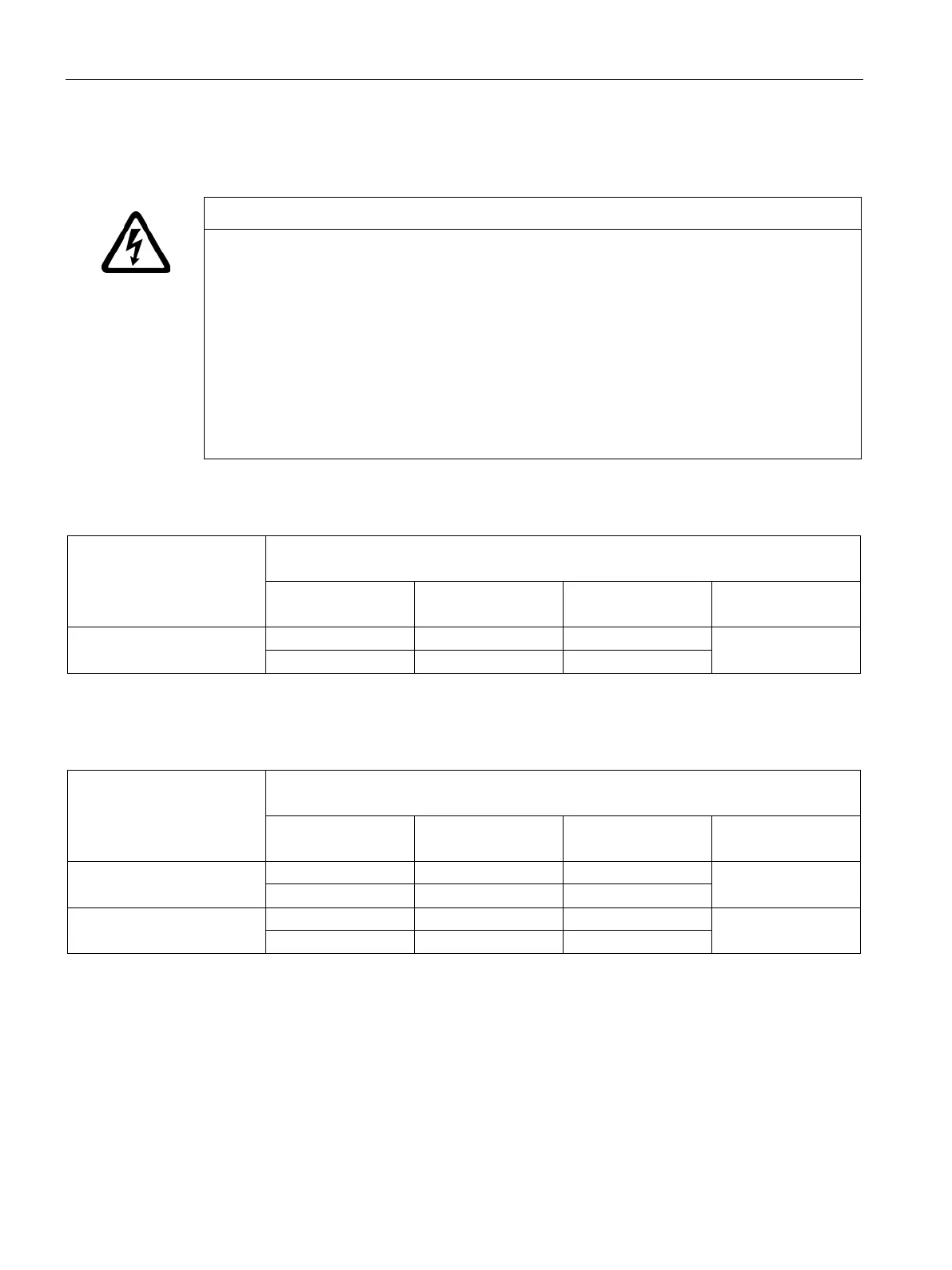
Excessively high supply voltage
Material damage can occur if the supply voltage is too high for the insulation system.
SIMOTICS machines can be operated with SINAMICS G converters and SINAMICS S
converters (uncontrolled and controlled infeed) when maintaining the permissible peak
voltages.
Carefully observe the values in the following tables.
Rise times t
r
> 0.1 µs.
The insulation system of SIMOTICS machines corresponds to the specifications laid down
in IEC 60034-18-41 according to voltage stress category C (IVIC C = high stress).
Table 6- 6 Maximum voltage peaks at the motor terminals for line (DOL) motors, converter operation possible
Maximum peak voltage at the motor terminals
max
dependent on the rise time t
r
Û
phase-to-phase
Û
phase-to-ground
Rise time t
r
DC link U
DC
≤ 500 V
750
Table 6- 7 Maximum voltage peaks at the motor terminals for motors specifically designed for converter operation (e.g.
VSD 10)
Maximum peak voltage at the motor terminals
Û
max
dependent on the rise time t
r
Û
phase-to-phase
pk
Û
phase-to-ground
pk
Rise time t
r
DC link U
DC
≤ 500 V
750
1000 1000 0.1
> 500 V to 690 V
1080
Further documents (Page 163)

 Loading...


