04/2005 Installation
SINAMICS G110 Operating Instructions
6SL3298-0AA11-0BP0
27
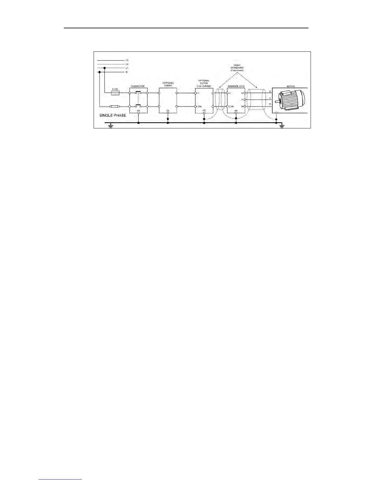
Figure 2-7 Motor and Power Connections
2.9.3 Avoiding Electro-Magnetic Interference (EMI)
The inverters are designed to operate in an industrial environment where a high
level of EMI can be expected. Usually, good installation practices will ensure safe
and trouble-free operation. If you encounter problems, follow the guidelines stated
below.
Action to Take
¾ Ensure that there is a good metal-to-metal connection between the inverter and
it’s (grounded) metal mounting surface.
¾ Ensure that all equipment in the cubicle is well grounded using short, thick
grounding cable connected to a common star point or busbar
¾ Make sure that any control equipment (such as a PLC) connected to the
inverter is connected to the same ground or star point as the inverter via a short
thick link.
¾ Connect the return ground from the motors controlled by the inverters directly to
the ground connection (PE) on the associated inverter
¾ Flat grounding conductors are preferred as they have lower impedance at
higher frequencies
¾ Terminate the ends of the cable neatly, ensuring that unscreened wires are as
short as possible
¾ Separate the control cables from the power cables as much as possible, using
separate trunking, cross them if necessary at 90º to each other.
¾ Whenever possible, use screened leads for the connections to the control
circuitry
¾ Ensure that the contactors in the cubicle are suppressed, either with R-C
suppressors for AC contactors or 'flywheel' diodes for DC contactors fitted to the
coils. Varistor suppressors are also effective.
¾ Use screened or armored cables for the motor connections and ground the
screen at both ends using the cable clamps
¾ For EMC compliant installation using the DIN Rail Mounting Kit, please refer to
Appendix B on page 80.

 Loading...


