Functions
7.9 Technological functions
Inverter with CU240B-2 and CU240E-2 Control Units
194 Operating Instructions, 07/2010, FW 4.3.2, A5E02299792B AA
7.9.1.4 Dynamic braking
Dynamic braking is typically used in applications in which dynamic motor behavior is
required at different speeds or continuous direction changes, e.g.:
● Horizontal conveyors
● Vertical and inclined conveyors
● Hoisting gear
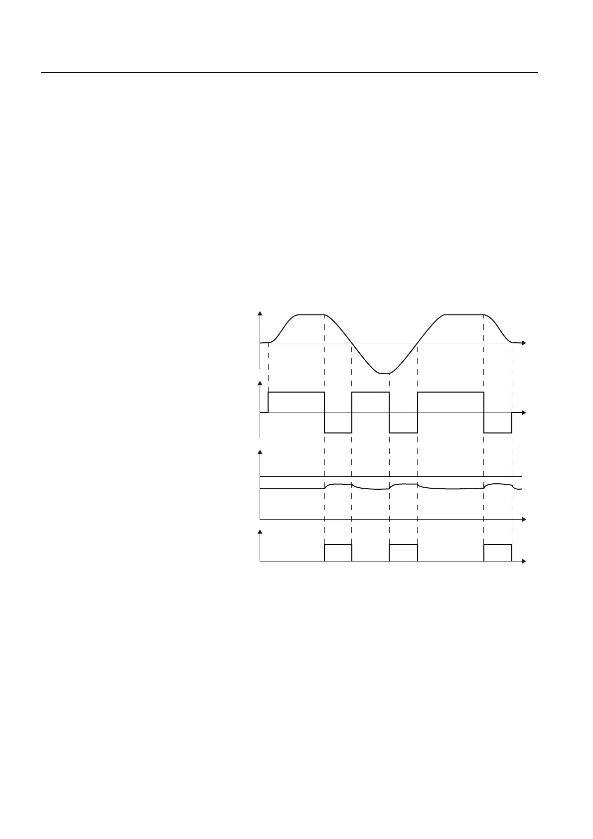
Principle of operation
The inverter controls the braking chopper depending on its DC link voltage. The DC link
voltage increases as soon as the inverter absorbs the regenerative power when braking the
motor. The braking chopper converts this power into heat in the braking resistor. This
therefore prevents the DC link voltage increasing above the limit value V
DC link, max
.
%UDNLQJFKRSSHUDFWLYH
0RWRUSRZHU
PRWRULQJ
5HJHQHUDWLQJ
6SHHGDFWXDOYDOXH
U
'&OLQNYROWDJH9
DC link
U
9
DC link, max
W
W
W
W
Figure 7-10 Simplified representation of dynamic braking with respect to time
Braking resistor connection
● Connect the braking resistor to terminals R1 and R2 of the Power Module
● Ground the braking resistor directly to the control cabinet's grounding bar. The braking
resistor must not be grounded via the PE terminals on the Power Module

 Loading...


