Alarms, faults and system messages
9.1 Operating states indicated on LEDs
Inverter with CU240B-2 and CU240E-2 Control Units
244 Operating Instructions, 07/2010, FW 4.3.2, A5E02299792B AA
9.1 Operating states indicated on LEDs
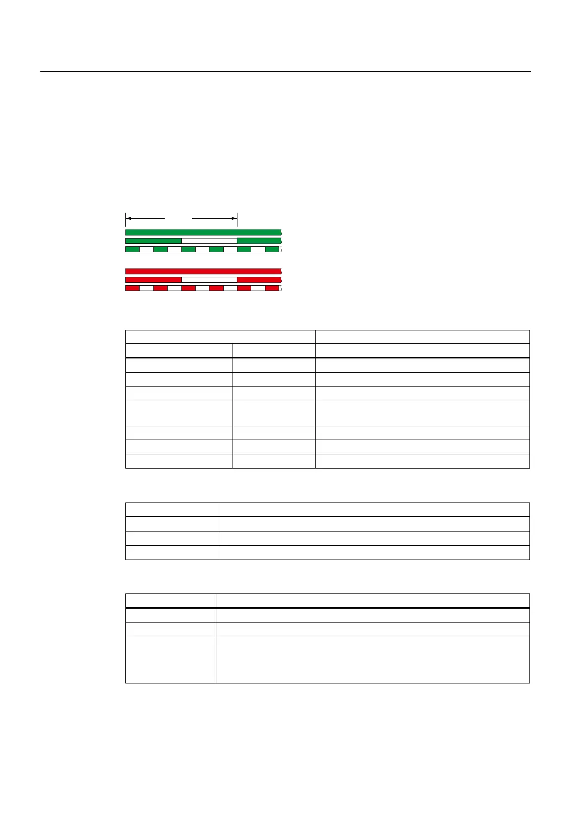
The LED RDY (Ready) is temporarily orange after the power supply voltage is switched-on.
As soon as the color of the LED RDY changes to either red or green, the LEDs on the
Control Unit indicate the inverter state.
LED RDY and LED BF displays
*5((1RQ
*5((1IODVKLQJVORZO\+]
*5((1IODVKLQJTXLFNO\+]
5('RQ
5('IODVKLQJVORZO\+]
5('IODVKLQJTXLFNO\+]
V
Table 9- 1 Inverter diagnostics
LED Explanation
RDY BF
GREEN - on --- Ready for operation (no active fault)
GREEN - slow --- Commissioning or reset to factory settings
RED - on OFF Firmware update in progress
RED - slow RED - slow Firmware Update is complete, Power ON Reset
required
RED - fast --- General fault
RED - fast RED - on Fault during firmware update
RED - fast RED - fast Incompatible firmware / incorrect memory card
Table 9- 2 Communication diagnostics via RS485
LED BF Explanation
OFF Receive process data
RED - slow Bus active - no process data
RED - fast No bus activity
Table 9- 3 Communication diagnostics via PROFIBUS DP
LED BF Explanation
off Cyclic data exchange (or PROFIBUS not used, p2030 = 0)
RED - slow Bus fault - configuration fault
RED - fast Bus fault
- no data exchange
- baud rate search
- no connection

 Loading...


