Installing/mounting
4.4 Mounting the Power Modules
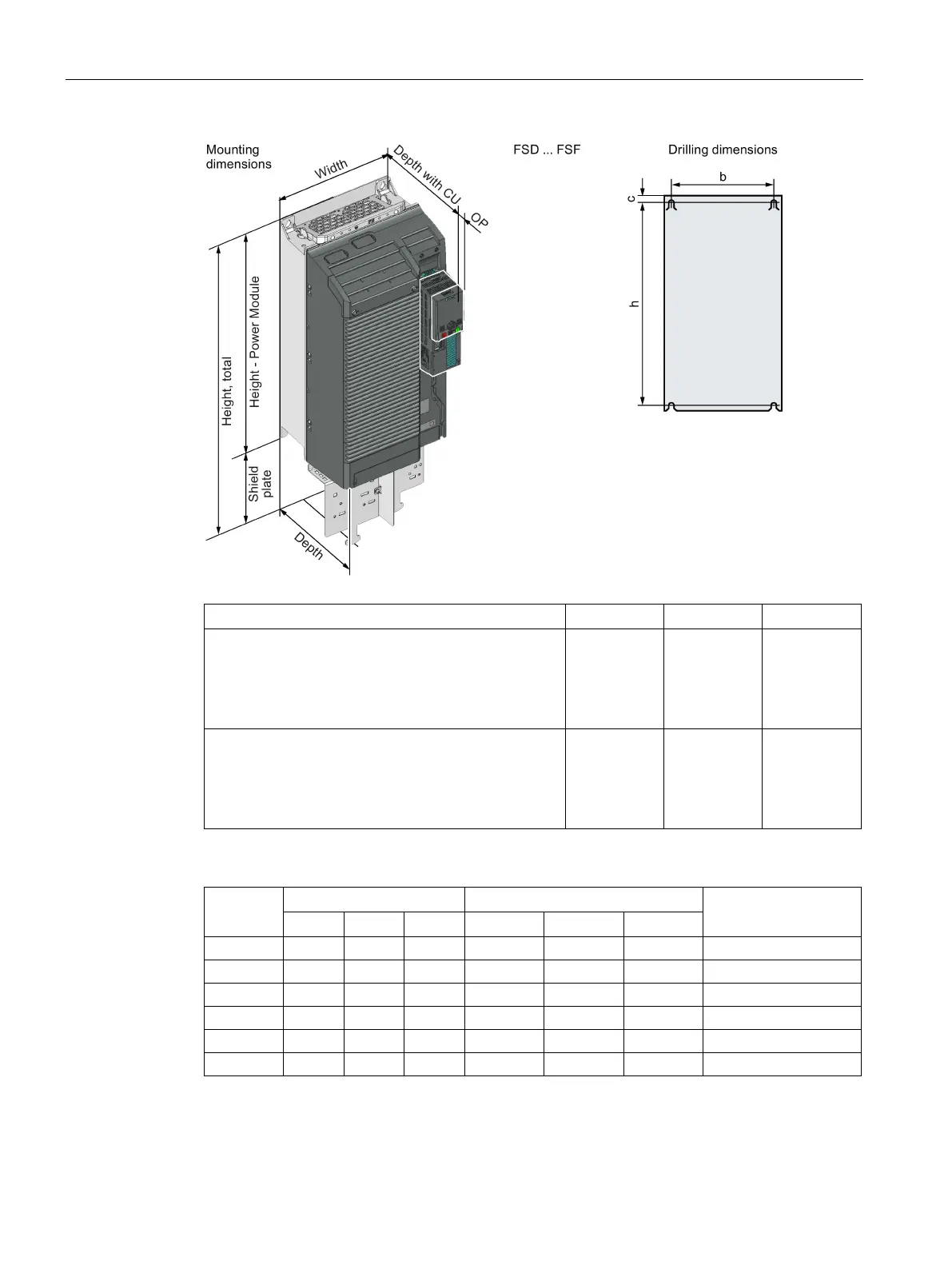
Power Module PM240-2
34 Hardware Installation Manual, 01/2017, A5E33294624B AE
Depth with Control Unit and Operator Panel (mm)
FSA … FSC
• With Control Unit:
• With Control Unit and blanking cover / BOP-2:
• With Control Unit and IOP:
+ 59
+ 70
+ 81
+ 41
+ 52
+ 63
+ 62
+ 73
+ 84
FSD … FSF
• With Control Unit:
• With Control Unit and blanking cover / BOP-2:
• With Control Unit and IOP:
+ 15.5
+ 26.5
+ 37.5
+ 0
+ 8.5
+ 19.5
+ 18.5
+ 29.5
+ 40.5
Table 4- 2 Drilling dimensions, cooling air clearances [mm] and fixing [Nm]
Cooling air clearances
1)
The Power Modules are designed for mounting without any lateral cooling air clearance. For toler-
ance reasons, we recommend a lateral clearance of approx. 1 mm.

 Loading...


