Hardware
6.2 Interfaces
Hydraulic Drive
System Manual, 04/2015, 6SL3097-4BA00-0BP1
215
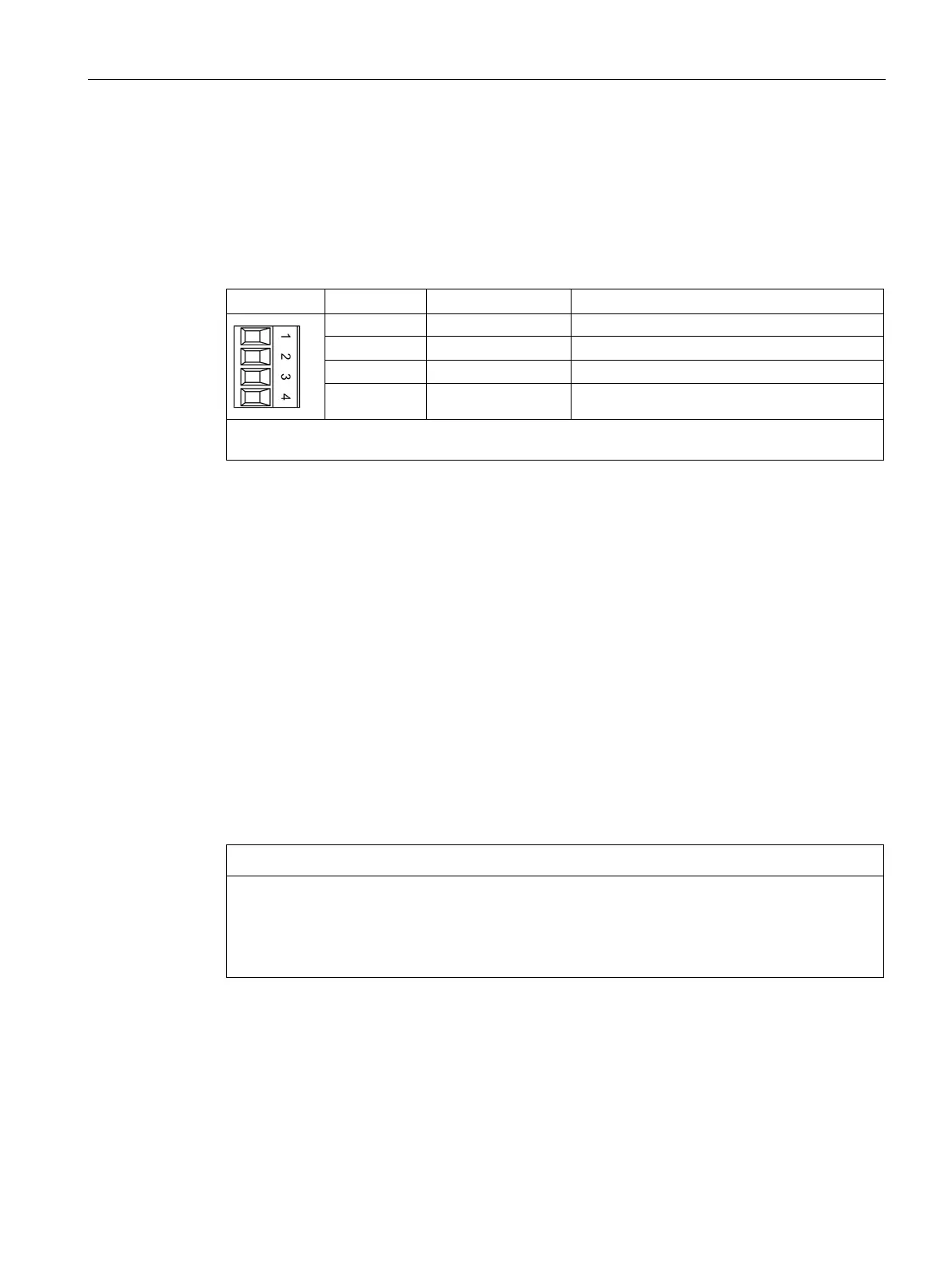
You can connect one shutoff valve for each axis using terminal X272. Contrary to other axial
connector distributions, both shutoff valves are located one above the other at one
connector.
Table 6- 11 X272: Shutoff valve connection
Output shutoff valve axis 1, P-switching
2 AV2P Output shutoff valve axis 2, P-switching
Output shutoff valve axis 1, ground
4 AV2N Output shutoff valve axis 2, ground
Max. connectable cross-section: 2.5 mm
2
The maximum permissible cable length is 40 m.
Use a 3-conductor, oiltight cable with the appropriate jacket to connect the shutoff valves.
Route the cable with jacket up to the connector.
Connect the PE conductor using a cable lug to the protective conductor connections
provided at the HLA module.
To achieve the surge strength specified in the appropriate standards, shielded cables must
be used for cable lengths > 30 m. The shield must be connected with the shield connection
bars at the upper side of the HLA module. Depending on the design, at the shutoff valve, the
shield can be connected at the connector. It is sufficient if the shield is connected at one end,
at the HLA module.
In order to prevent the connectors being inadvertently interchanged at terminal X271 or
X272, when supplied, both terminals and the associated connectors are equipped with
coding elements.
Interchanging the connectors at terminals X271 and X272
If the connections at terminal blocks X271 and X272 are interchanged, when the 26.5 V is
connected, the shutoff valves can immediately open.
• Correctly connect the conductors/cables to terminal blocks X271 and X272.

 Loading...


