Hardware
6.2 Interfaces
Hydraulic Drive
216 System Manual, 04/2015, 6SL3097-4BA00-0BP1
X281 and X282 sensors for shutoff valves
For especially safety-critical applications, you can use shutoff valves whose spool position is
monitored using inductive sensors. The sensors, certified from a safety-related perspective,
signal the "open" and "closed" valve states using 2 signal outputs. The signals emulate the
hysteresis of the mechanical overlap. Excluding the overlap instants when opening or
closing, the signal outputs are complementary with respect to one another.
The connector at the HLA module contains:
● Short-circuit proof 26.5 V supply
● Ground
● 2 inputs for the NO and NC signals
This means that all of the cables are directly connected using one connector.
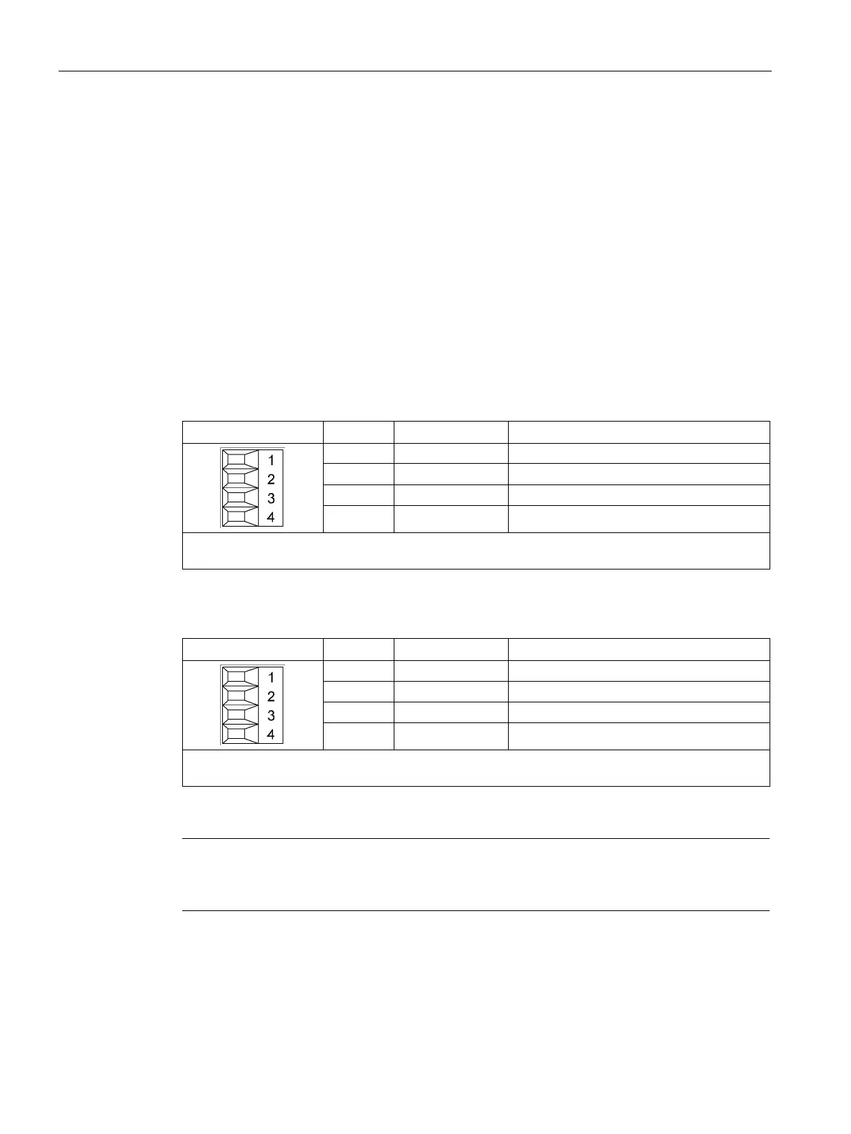
Table 6- 12 X281: Sensors for the spool position of the shutoff valves, axis 1
+26.5 V supply for the sensors
2 AVS1NC Sensor input axis 1, NC
4 M Supply, sensor ground
Max. connectable cross-section: 1.5 mm
2
Table 6- 13 X282: Sensors for the spool position of the shutoff valves, axis 2
+26.5 V supply for the sensors
4 M Supply, sensor ground
Max. connectable cross-section: 1.5 mm
2
Note
Maximum cable lengths
The maximum permissible cable length is 40 m.

 Loading...


