Appendix
A.3 Hydraulic
Hydraulic Drive
System Manual, 04/2015, 6SL3097-4BA00-0BP1
237
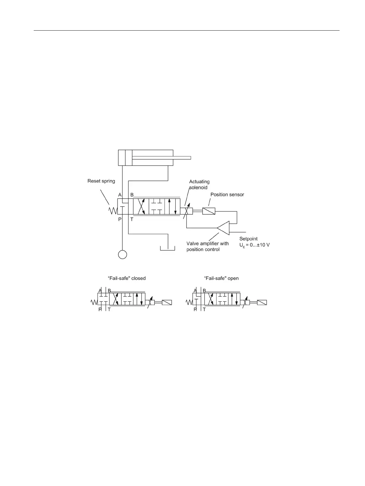
The operating principle of the servo solenoid valve is represented by a symbol in the
hydraulic circuit diagram. The symbol comprises a series of different boxes denoting the
valve positions.
The three stepless-transition valve positions are represented by additional lines. The symbol
also indicates how the valve is actuated. In this case, by direct solenoid actuation with spring
return at one end.
If the valve has a fail-safe position, then the valve spool moves into a fourth (safety) position
when the valve is not powered. There are two alternative positions.
The symbol also illustrates the principle of position control applied to the valve spool.
Figure A-3 Symbol

 Loading...


