Technical Appendix
6.2 PLC user interface signals
6-132
SINUMERIK 802S
6FC5 597–2AA00–0BP2 (01.02)
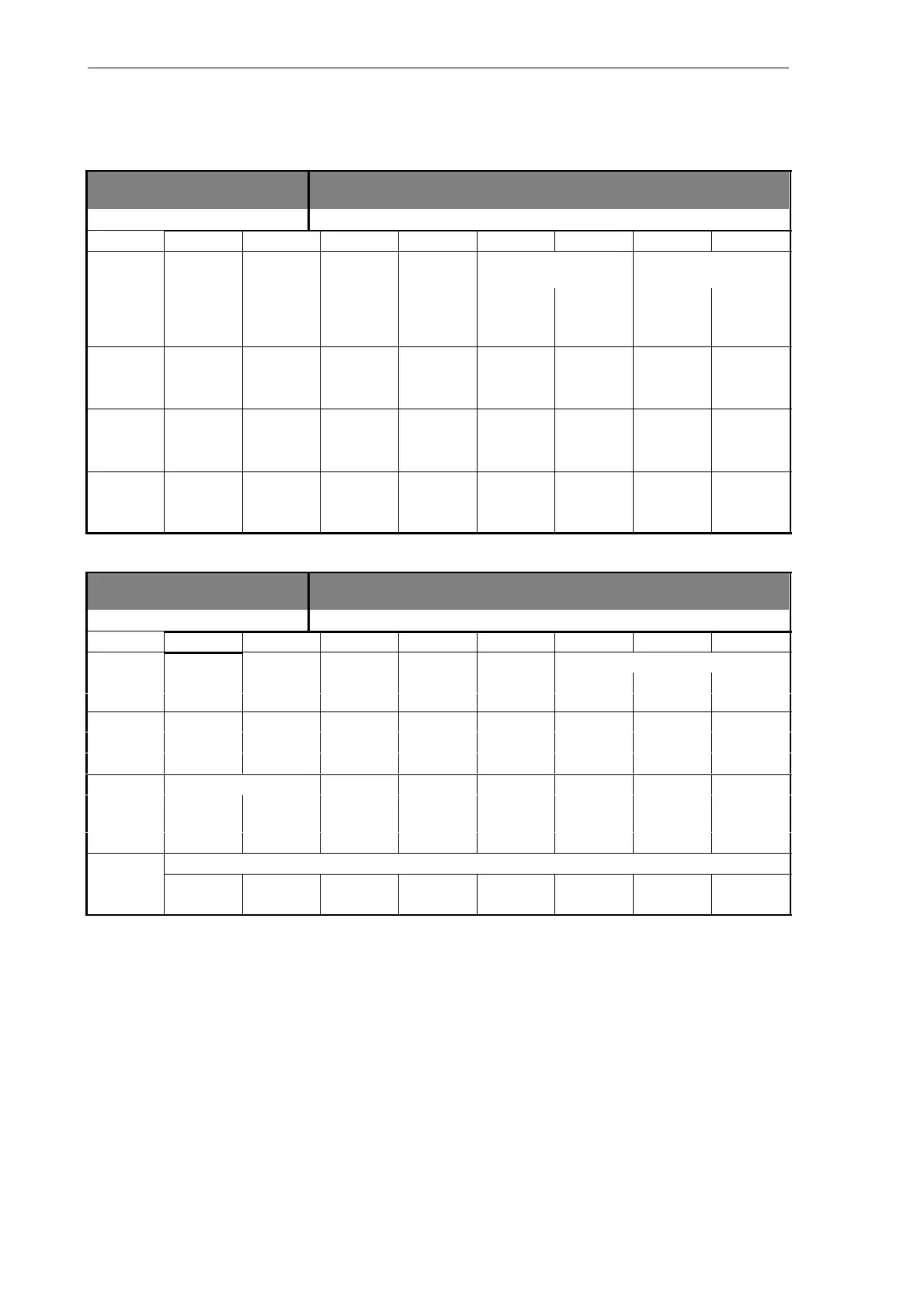
Signals to axis
3800...3802 Signals to axis [r/w]
Data block
Interface PLC –––––> NCK
Byte Bit 7 Bit 6 Bit 5 Bit 4 Bit 3 Bit 2 Bit 1 Bit 0
Delay 2nd software limit
switch
Hardware limit switch
380x1000 Ref.–point
approach
(axis)
plus minus plus minus
380x1001
(axis)
380x1002
(axis)
380x1003
(axis)
Signals to spindle
3803 Signals to spindle [r/w]
Data block
Interface PLC –––––> NCK
Byte Bit 7 Bit 6 Bit 5 Bit 4 Bit 3 Bit 2 Bit 1 Bit 0
Gear is Actual gear stage
38032000
changed
(spindle) C B A
Spindle feed
38032001 Invert
override
(spindle)
M3/M4
valid
Set direction of rotation
38032002 Recipro-
cating
Recipro-
cating
(spindle)
CCW CW speed by PLC
Spindle override
38032003
(spindle)
H G F E D C B A