Installing the STEPDRIVE C Drives
3.3 Starting up the drive modules
3-45
SINUMERIK 802S
6FC5 597–2AA00–0BP2 (01.02)
3.3 Starting up the drive modules
Prerequisite
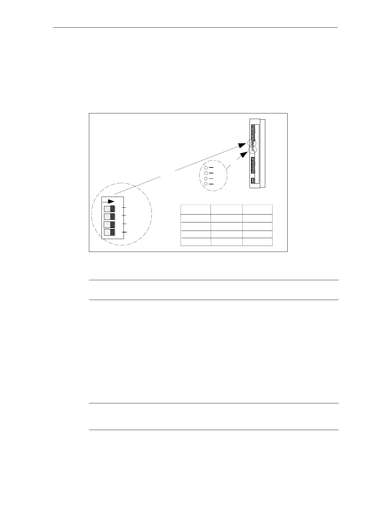
S Proper connection of the cables as shown in Fig. 3-2.
S Setting of the current in accordance with the motor type using the DIL switch
CURR.1
CURR.2
RES.
DIR.
ON
Motor Type
CURR 1
CURR 2
3.5 Nm
9 Nm
12Nm
OFF
ON
OFF
OFF
OFF
ON
ON
ON
6 Nm
RDY
TMP
FLT
DIS
LEDs
DIL switch
Fig. 3-3 DIL switch and LEDs
Warning
If the current is set too large for the motor, the motor can be damaged due to overtemperature.
Start–up sequence
1. Connect the mains voltage and – if necessary – also the 24 V supply voltage.
2. Check the DIS LED.
3. Activate the ENABLE signal via the control system (power–up the control system).
The yellow DIS LED goes out and the green RDY LED is lit. The drive is ready, the motor
is powered.
If the PULSE signal is provided by the control system with pulses, then motor will rotate in
the direction of rotation specified by the DIR signal.
Note
The DIR switch can be used to adapt the direction of rotation to the mechanics of the machine. Never actuate
the switch when the drive is powered!