Technical Appendix
6.2 PLC user interface signals
6-134
SINUMERIK 802S
6FC5 597–2AA00–0BP2 (01.02)
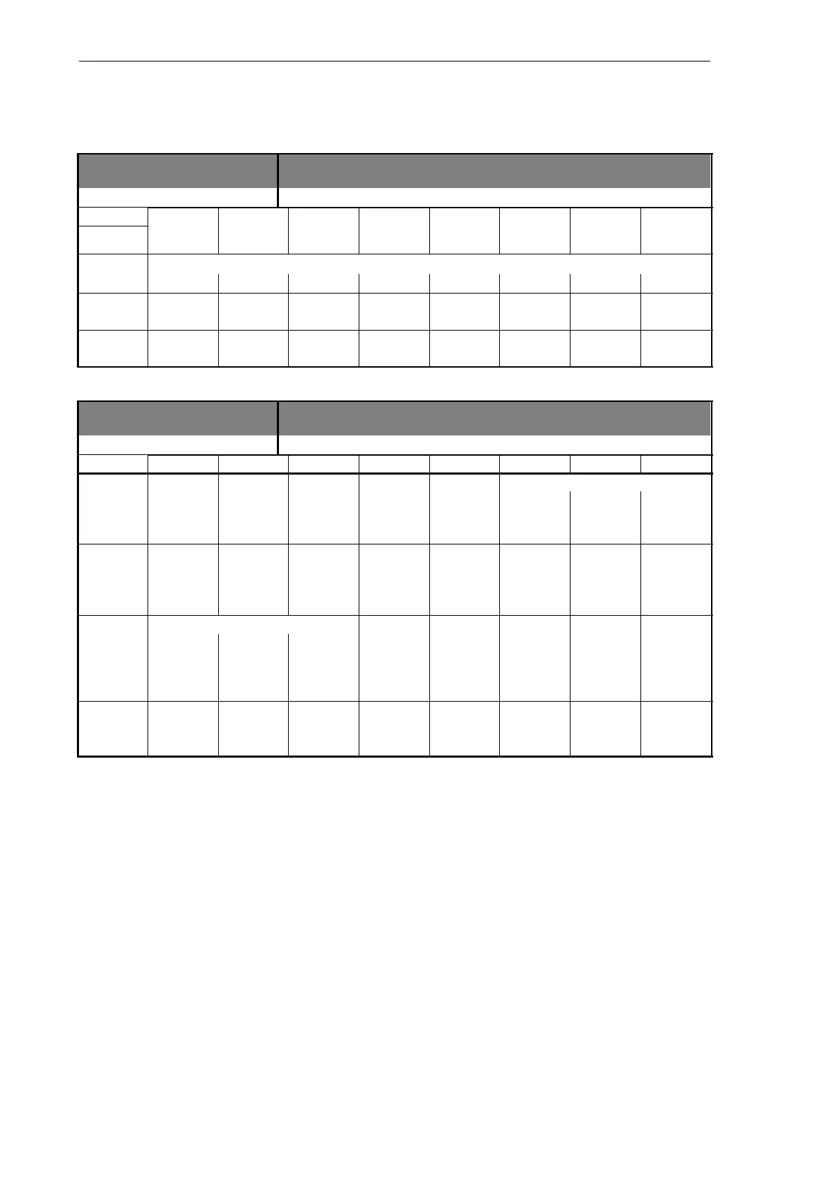
Signals from axis
3900...3903 Signals from axis [r]
Data block
Interface NCK –––––> PLC
Byte Bit 7 Bit 6 Bit 5 Bit 4 Bit 3 Bit 2 Bit 1 Bit 0
390x1000
(axis)
390x1001
(axis)
390x1002 Lubrica-
(axis)
tion pulse
390x1003
(axis)
Signals from spindle
3903 Signals from spindle [r]
Data block
Interface NCK –––––> PLC
Byte Bit 7 Bit 6 Bit 5 Bit 4 Bit 3 Bit 2 Bit 1 Bit 0
Set gear stage
39032000 Change
gear
(spindle)
C B A
Actual di-
rection
Spindle Set Set Speed
39032001 of rotation within set speed speed limit
(spindle)
CW range increased limited exceeded
Active spindle mode Tapping
39032002 Control Recipro-
cating
Position-
ing
without
compen-
sating
(spindle)
mode mode mode chuck
39032003
(spindle)