Installing the Control System
2.3 Connecting the individual components
2-26
SINUMERIK 802S
6FC5 597–2AA00–0BP2 (01.02)
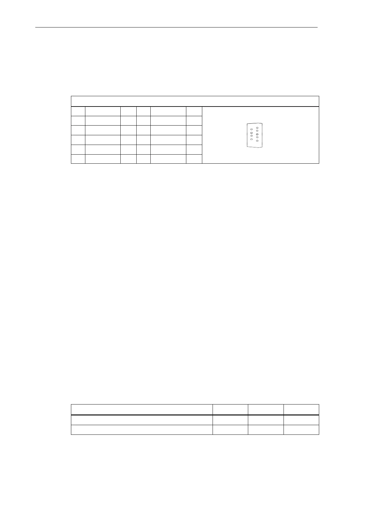
Connector designation: X3
SPINDLE
Connector type: 9–pin D-Sub plug connector
Table 2-5 Belegung des Steckers X3
X3
Pin Signal Type Pin Signal Type
1 SW VO 6 BS VO
2 7
1
6
3 8
5
9
4 9 RF.1 K
5
9
5 RF.2 K
for analog drives:
SW Setpoint
BS Reference potential for setpoint (analog ground)
RF.1, RF.2 Servo enable contact
Signal type
VO Voltage output
K Switching contact
Drives with analog interface
Signals:
One voltage and one enable signal is provided.
S SW (SETPOINT)
Analog voltage signal in the range of "10 V to output a speed setpoint
S BS (REFERENCE SIGNAL)
Reference potential (analog ground) for the setpoint signal, internally connected to the log-
ics ground
S RF (SERVO ENABLE)
Relay contact pair used to switch the enable signal for the power section, e.g. a
SIMODRIVE unit. This signal is used by the ENC when the cyclic control mode is started.
Signal parameters
The setpoint is output as an analog differential signal.
Table 2-6 Electrical parameters of the spindle setpoint signal
Parameter
Min. Max. Unit
Voltage range -10.5 10.5
V
Output current -3 3 mA
Relay contact