Description: This setting data defines the assignment of the tool length components to the geometry
axes irrespective of
the tool type. It can assume any value between 0 and 3. Any other
value is interpreted as 0.
Value
0: Standard assignment. A distinction is made between turning and grinding tools
(tool types 400 to 599) and other tools (milling tools).
1: The tool length components are assigned irrespective of the actual tool type,
always as for milling tools.
2. The tool length components are assigned irrespective of the actual tool type,
always as for turning tools.
3. The tool length components are assigned separately, on the one hand for turning
and
grinding tools
(tool types 400 to 599) and, on the other hand, for all other tools
(milling tools).
The assignment of tool components is specified as follows:
Milling tools:
The assignment of tool length components is specified by SD42940
$SC_TOOL_LENGTH_CONST.
Turning tools:
The assignment of tool length components is specified by SD42942
$SC_TOOL_LENGTH_CONST_T.
The setting data also affects the wear values assigned to the length components.
If SD42940 $SC_TOOL_LENGTH_CONST is set, the tables defined there access the table for
milling
and
turning
tools defined by SD42950 $SC_TOOL_LENGTH_TYPE irrespective of the
actual tool type if the value of the latter is 1 or 2.
42954 TOOL_ORI_CONST_M - W1
- Change of the tool orientation component for milling tools on plane
change
DWORD Immediately
-
808d-me42 - 0, 0, 0, 0, 0, 0, 0, 0... - - 0/0 S
808d-me62 - 0, 0, 0, 0, 0, 0, 0, 0... - - 0/0 S
808d-te42 - 0 - - 0/0 S
808d-te62 - 0 - - 0/0 S
808d-mte40 - 0, 0, 0, 0, 0, 0, 0, 0... - - 7/7 U
808d-mte60 - 0, 0, 0, 0, 0, 0, 0, 0... - - 7/7 U
Description: If this setting data is not equal to zero, a clockwise, orthogonal tool coordinate
system is defined
for milling tools (all tool types except 400 to 599), which remains
unchanged when the machining plane is changed (G17 - G19. It has no relevance for
turning and grinding tools.
The orientation coordinate system is determined by the orientation vector and a normal
orientation vector extending
perpendicularly to it. It is completed by a third vector,
the binormal vector, which derives from the cross product of the normal orientation
vector and the orientation vector.
The basic orientation is determined by the units and tens digits of the setting data.
Apart from the
value 0, only the values 17, 18 and 19 are permissible. All other values
are treated as if their value were 17.
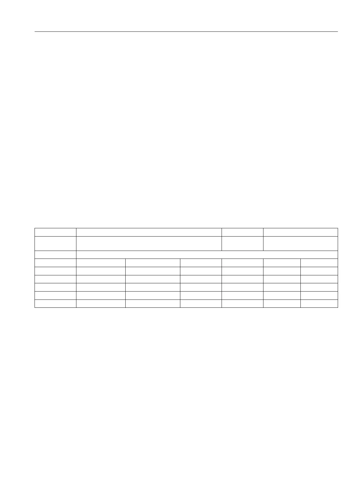
Orientation Normal orient- Binormal
Content vector ation vector vector
17* (0, 0, 1) (0, 1, 0) (1, 0, 0)
18 (0, 1, 0) (1, 0, 0) (0, 0, 1)
19 (1, 0, 0) (0, 0, 1) (0, 1, 0)
* Each value not equal to 0 that is not one of the listed values is evaluated as if it
were the value 17.
NC setting data
Parameter Manual
Parameter Manual, 08/2015, 6FC5397-8EP40-0BA1 335

 Loading...


