Note
The programming engineer (NCK and PLC) is responsible for organizing (structuring) this
memory area. Every storage position in the memory can be addressed provided that the limit
is selected according to the appropriate data format (i.e. a 'DWORD' for a 4byte limit, a WORD
for a 2byte limit, etc.). The memory area is always accessed with the information about the
data type and the position offset within the memory area.
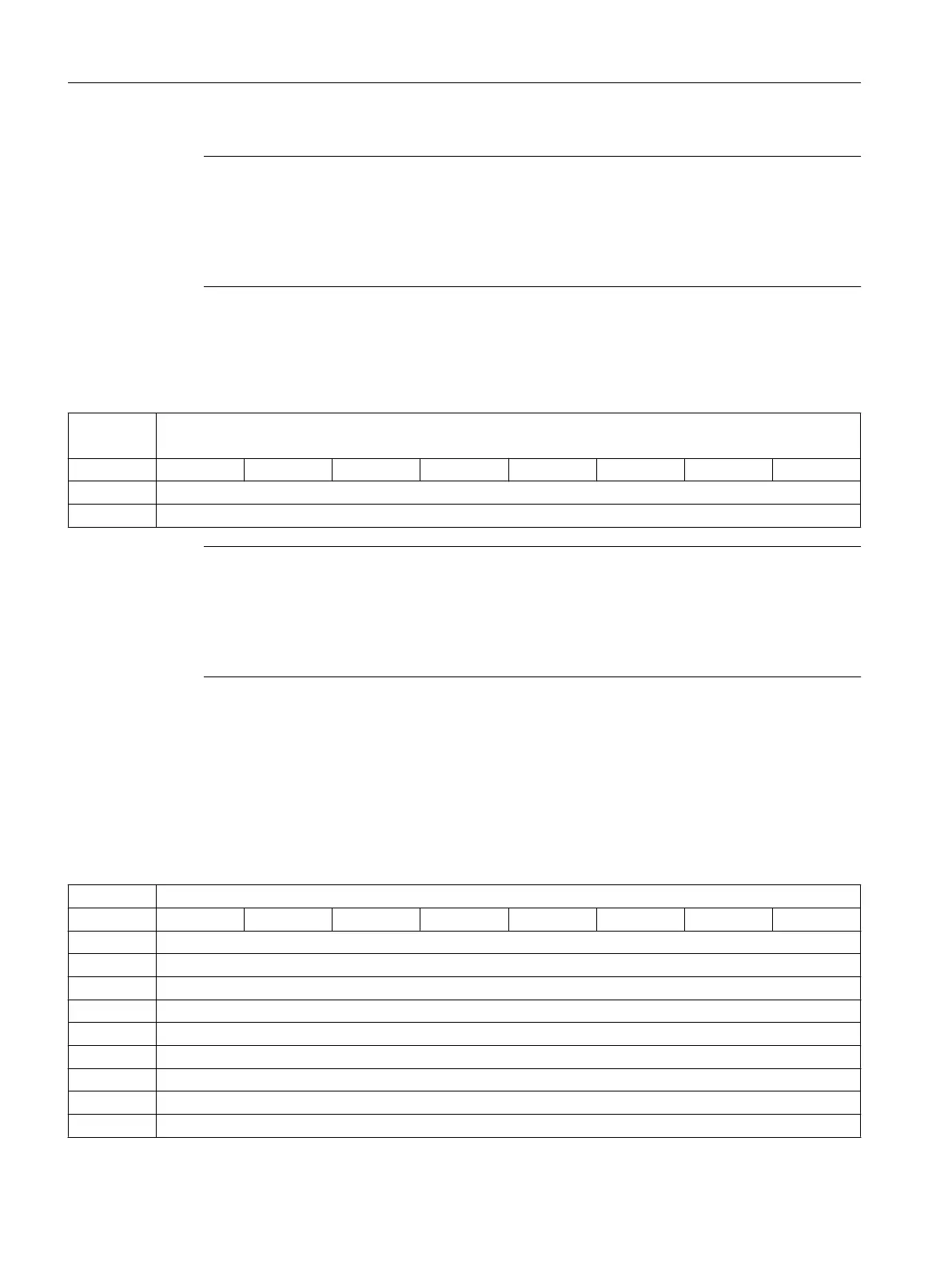
6.12 Axis actual values and distance-to-go
DB5700 ...
5704
Signals from axis/spindle [r]
NCK -> PLC interface
Byte Bit 7 Bit 6 Bit 5 Bit 4 Bit 3 Bit 2 Bit 1 Bit 0
0 Axis actual value (REAL)
4 Axis distance-to-go (REAL)
Note
The axis actual values and distances-to-go can be separately requested:
● DB2600.DBX0001.1 Request axis actual values
● DB2600.DBX0001.2 Request axis distances-to-go
If the particular request is set, then the NCK supplies these values for all axes.
6.13 Maintenance scheduler: User interface
6.13.1 Initial (start) data
DB9903 Initial data table [r16]
Byte Bit 7
Bit 6 Bit 5 Bit 4 Bit 3 Bit 2 Bit 1 Bit 0
0 Interval 1 [h]
2 Time of first warning 1 [h]
4 Number of warnings to be output 1
6 Reserved 1
8 Interval 2 [h]
10 Time of first warning 2 [h]
11 Number of warnings to be output 2
14 Reserved 2
... ...
PLC user interface
6.13 Maintenance scheduler: User interface
Parameter Manual
484 Parameter Manual, 08/2015, 6FC5397-8EP40-0BA1

 Loading...


