corresponding to ... DB390x DBX4002.6 (n
act
= n
set
)
DB390x DBX4002.3 (M
d
= M
dx
)
Note for the reader Commissioning Manual, Turning and Milling
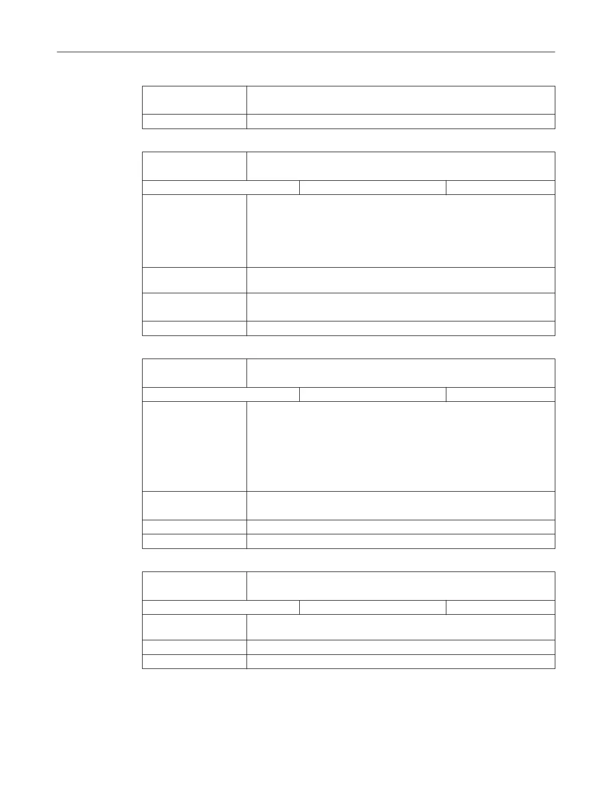
DB390x
DBX4002.2
Ramp-up completed
Signal(s) to drive (NCK → PLC)
Edge evaluation: No Signal(s) updated: Cyclic
Signal state 1 The PLC is signaled that after a new speed setpoint input, the speed actual
value has reached
the speed tolerance bandwidth and has remained within
this tolerance bandwidth for the specified time.
Even if the speed actual value leaves the tolerance bandwidth (because of
speed fluctuations resulting from load changes) the "ramp-up completed"
signal remains.
Signal state 0 The conditions described above have not yet been fulfilled. Ramp-up has
therefore not yet been completed.
corresponding to ... DB390x DBX4002.6 (n
act
= n
set
)
DB390x DBX4002.3 (M
d
< M
dx
)
Note for the reader Commissioning Manual, Turning and Milling
DB390x
DBX4002.3
M
d
< M
dx
Signal(s) to drive (NCK → PLC)
Edge evaluation: No Signal(s) updated: Cyclic
Signal state 1 The drive signals to the PLC that the torque setpoint M
d
does not
exceed the
threshold torque M
dx
in the steady-state condition (i.e. ramp-up completed).
The torque threshold characteristic is speed-dependent.
While ramping-up, the IS "M
d
< M
dx
" remains at 1.
The signal only becomes active after ramp-up has been completed (DB390x
DBX4002.2 = 1) and the signal interlock time for the threshold torque has
expired.
Signal state 0 The torque setpoint M
d
is greater than the threshold torque M
dx
.
If necessary, the PLC user program can initiate a response.
corresponding to ... DB390x DBX4002.2 (ramp-up completed)
Note for the reader Commissioning Manual, Turning and Milling
DB390x
DBX4002.4
n
act
< n
min
Signal(s) to drive (NCK → PLC)
Edge evaluation: No Signal(s) updated: Cyclic
Signal state 1 The drive signals to the PLC that the actual speed value n
act
is less
than the
minimum speed (n
min
).
Signal state 0 The speed actual value is higher than the minimum speed.
Note for the reader Commissioning Manual, Turning and Milling
Detailed descriptions of interface signals
5.8 Axis / spindle-specific signals
Parameter Manual
Parameter Manual, 08/2015, 6FC5397-8EP40-0BA1 445
 Loading...


