PLC User Interface
5.1 Addressing ranges
Parameter Manual
422
Operating Instructions, 08/2013, 6FC5397-8EP40-0BA0
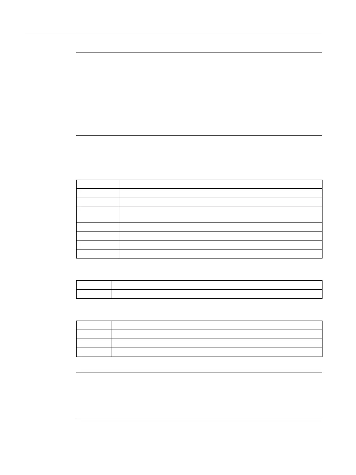
Special bit memory SM bit definition (read-only)
Special Marker SM Bit Definition
Variable access rights
Data format information
Note
The permitted offset for an address depends on the access:
• Bit or byte access: any offset.
Byte-size variables are placed one beside another seamlessly in a DB.
• Word access: the offset must be divisible by 2.
Word-size variables (2 bytes) are always saved on straight offsets.
• Double word access: the offset must be divisible by 4.
Double word-size variables (4 bytes) are always saved on offsets that are divisible by 4.
SM bits Description
SM 0.0 Bit memory with the defined ONE signal
SM 0.1 Initial setting: first PLC cycle '1', subsequent cycles '0'
SM 0.2 buffered data lost - only valid in first PLC cycle
('0' data ok, '1' data lost)
SM 0.3 POWER ON: first PLC cycle '1', subsequent cycles '0'
SM 0.4 60 s clock (alternating '0' for 30 s, then '1' for 30 s)
SM 0.5 1 s clock (alternating '0' for 0.5 s, then '1' for 0.5 s)
SM 0.6 PLC cycle clock (alternating one cycle '0', then one cycle'1')
[r] You can "read only" designated area
[r/w] You can "read and write" designated area
1BIT
8 BYTE
16 INT/WORD
32 DINT/DWORD/REAL
Note
All of the empty fields in the user interface are "reserved for Siemens" and may neither be
writted to nor evaluated.
Fields designated with "0" always have the value "logical 0".
If there is no data format information, you can read or write to all the specified data formats.