Parameter Manual
Operating Instructions, 08/2013, 6FC5397-8EP40-0BA0
451
PLC User Interface
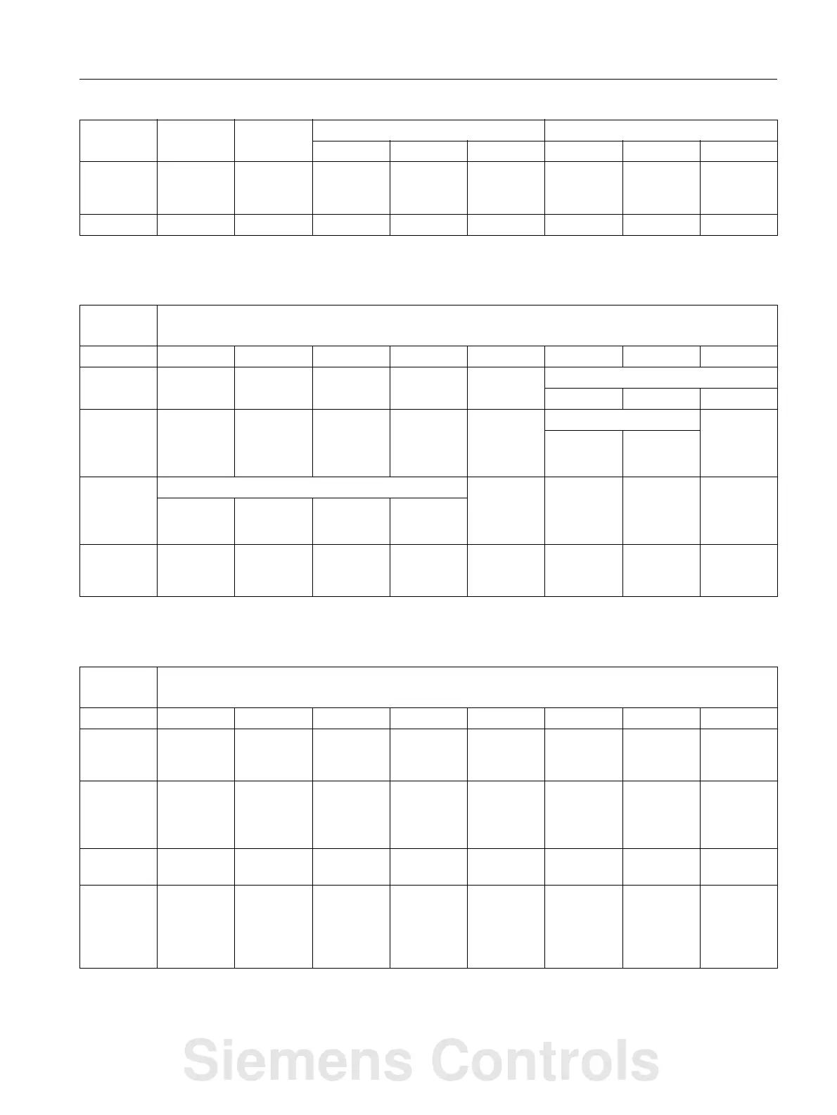
5.9 Axis/spindle signals
Signals from spindle
Signals from drive
1001
1002 Rotary axis
in position
Indexing
axis in
position
Positioning
axis
Path axis Lubrication
pulse
1003
DB3900 ...
3903
Signals from spindle [r]
NCK -> PLC interface
Byte Bit 7 Bit 6 Bit 5 Bit 4 Bit 3 Bit 2 Bit 1 Bit 0
2000 Change
gear stage
Setpoint gear stage
CBA
2001 Actual
direction of
rotation,
clockwise
Speed
monitoring
Spindle in
setpoint
range
Overlay
range limit
violated
Setpoint Speed limit
exceeded
Increased Limited
2002 Active spindle mode Rigid
tapping
GWPS
active
Const.
Cutting
velocity
active
Control
mode
Oscillation
mode
Positioning
mode
2003 Spindle in
position
reache
Tool with
dynamic
limiting
DB3900 ...
3903
Signals from axis/spindle [r]
NCK -> PLC interface
Byte Bit 7 Bit 6 Bit 5 Bit 4 Bit 3 Bit 2 Bit 1 Bit 0
4000 Holding
brake
opened
RLI active
4001 Pulse
enabled
Speed
controller
integrator
disabled
Drive ready
4002 nact = n
set
n
act
< n
x
n
act
< n
min
M
d
< M
dx
Ramp-up
completed
4003 Generator
operation,
minimum
speed
falled below
VDClink <
alarm
threshold
Siemens Controls
 Loading...


